
Back-up power system

a power system and power supply technology, applied in the direction of emergency power supply arrangements, electric vehicles, transportation and packaging, etc., can solve the problems of requiring rewiring of the building, complicated, and most disturbing consequences, and achieve the effect of optimizing power output and maximizing battery life during a main power failure period

Inactive Publication Date: 2008-12-04
ELECTRIKUS
View PDF14 Cites 46 Cited by
  • Summary
  • Abstract
  • Description
  • Claims
  • Application Information

AI Technical Summary

Benefits of technology

[0012]Embodiments of the present invention include a system comprising a rechargeable battery including, but not limited to, a sealed lead acid battery, a nickel metal hydride battery, a lithium ion battery, and the like. In an embodiment of the present invention, a switch limits output current to one of a plurality of settings to provide for the maximum flexibility in backup power time vs. power output. In another embodiment, the plurality of settings include a first setting to provide a full power voltage to a chosen appliance, a second setting to provide a medium power voltage to the appliance, and a third setting to provide a low power voltage to the appliance, in order to extend the power supplied to the appliance during a main power failure. For example, in using a system of an embodiment with a house lamp, the first setting may produce a power output equivalent to a 60 Watt (“W”) incandescent bulb. The second setting limits the power output to a 25W equivalent incandescent bulb, and the third setting, in cases where there is an extended main power failure, may provide the light level of a couple of candles or a night light.

Problems solved by technology

Power outages during times of floods, high wind, wildfires, ice and snow storms, and other natural disasters are relatively common even in the U.S. When power fails, one of the most disturbing consequences is being left in the dark, especially for the elderly or families with small children.
However, such systems are designed primarily for commercial application, either directly built into the lighting fixture, a light bulb, or into the control switch and automatically sense loss of power so that there is always some light to evacuate the building.
They are complicated, expensive and may require rewiring the building.
These are not well suited for the home.
However, light output is very low corresponding to a night light or a single candle.
In this case there is considerable physical exertion just to maintain enough light to see.
The problem with these systems is twofold.
First, the consumer does not have the freedom to choose the lamp to match interior decor, and even if the backup unit is built into the bulb, the system typically is bulky, the consumer cannot choose the type or light output of the bulb, or a shade may not fit on many lamp systems.
Further, due to mechanical size constraints, there is a limited battery size and therefore, a limited length of backup time, typically less than an hour.
However, drawbacks include large, bulky bulbs that may not fit many household appliances, as well as harsh fluorescent light.
Finally, there are standby emergency generators that can be directly wired into the main power of a dwelling or building, but these are expensive.
Additionally, because the generator power is provided to the entire home without selectivity as to what appliance is powered, the length of time for back-up is generally only two to three days with a single charge of fuel.

Method used


Image

  • Back-up power system
  • Back-up power system
  • Back-up power system

Examples


Embodiment Construction

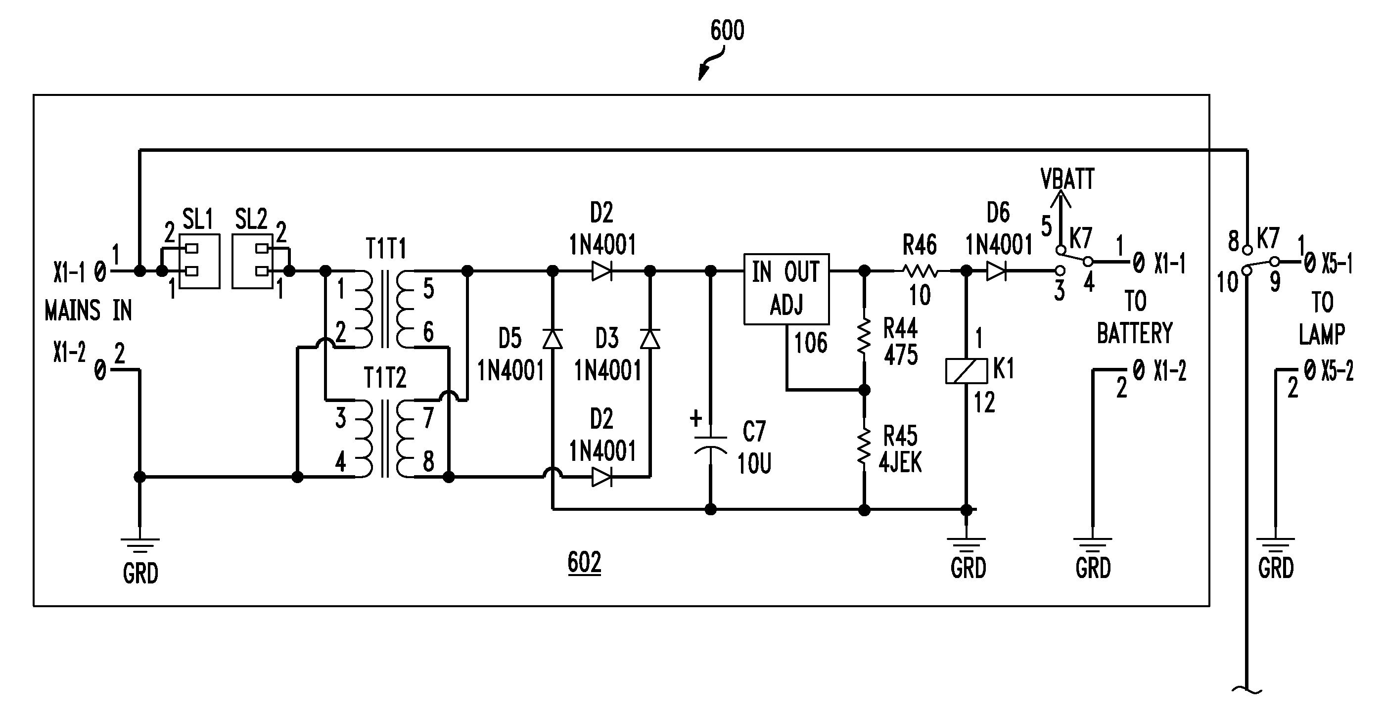
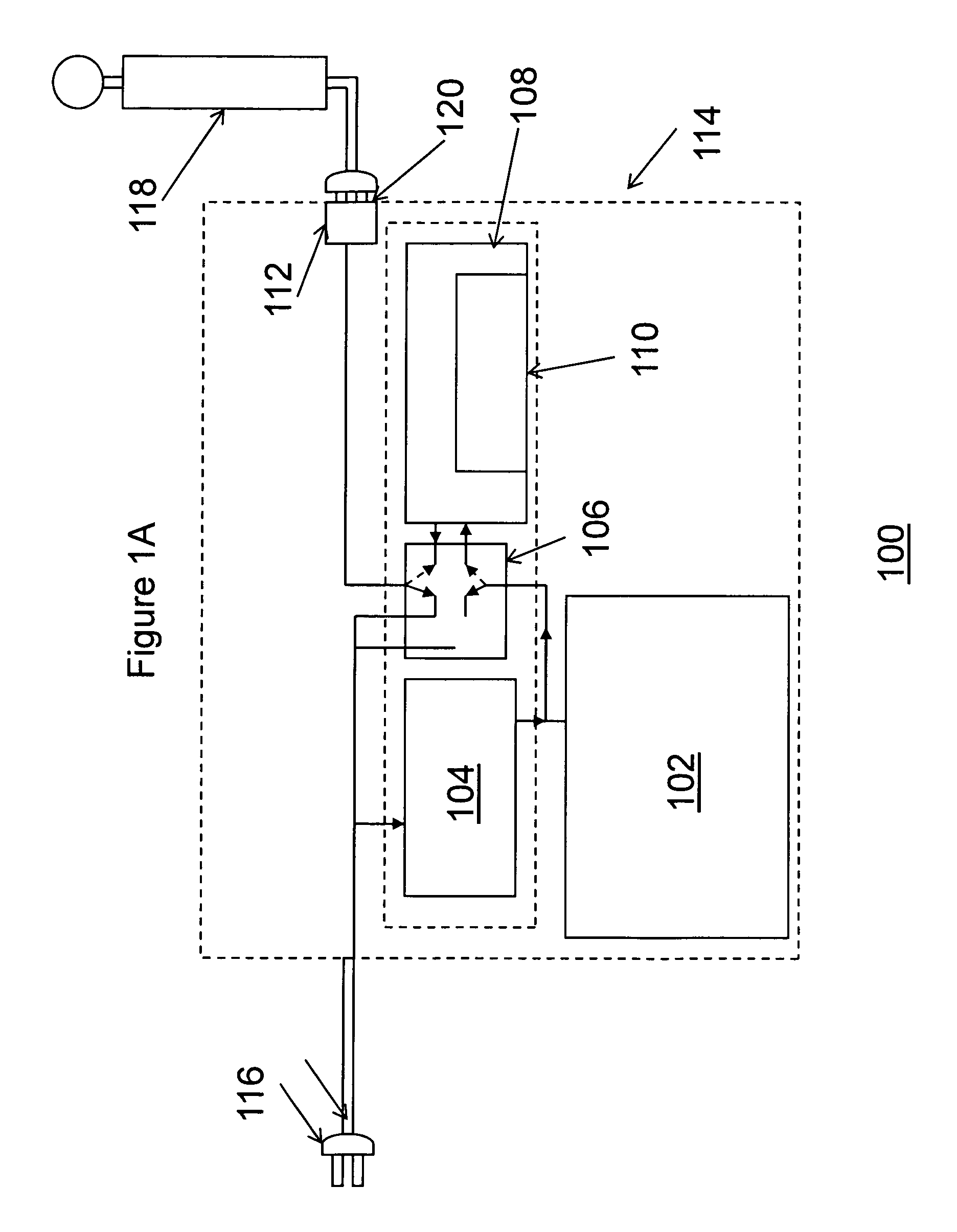
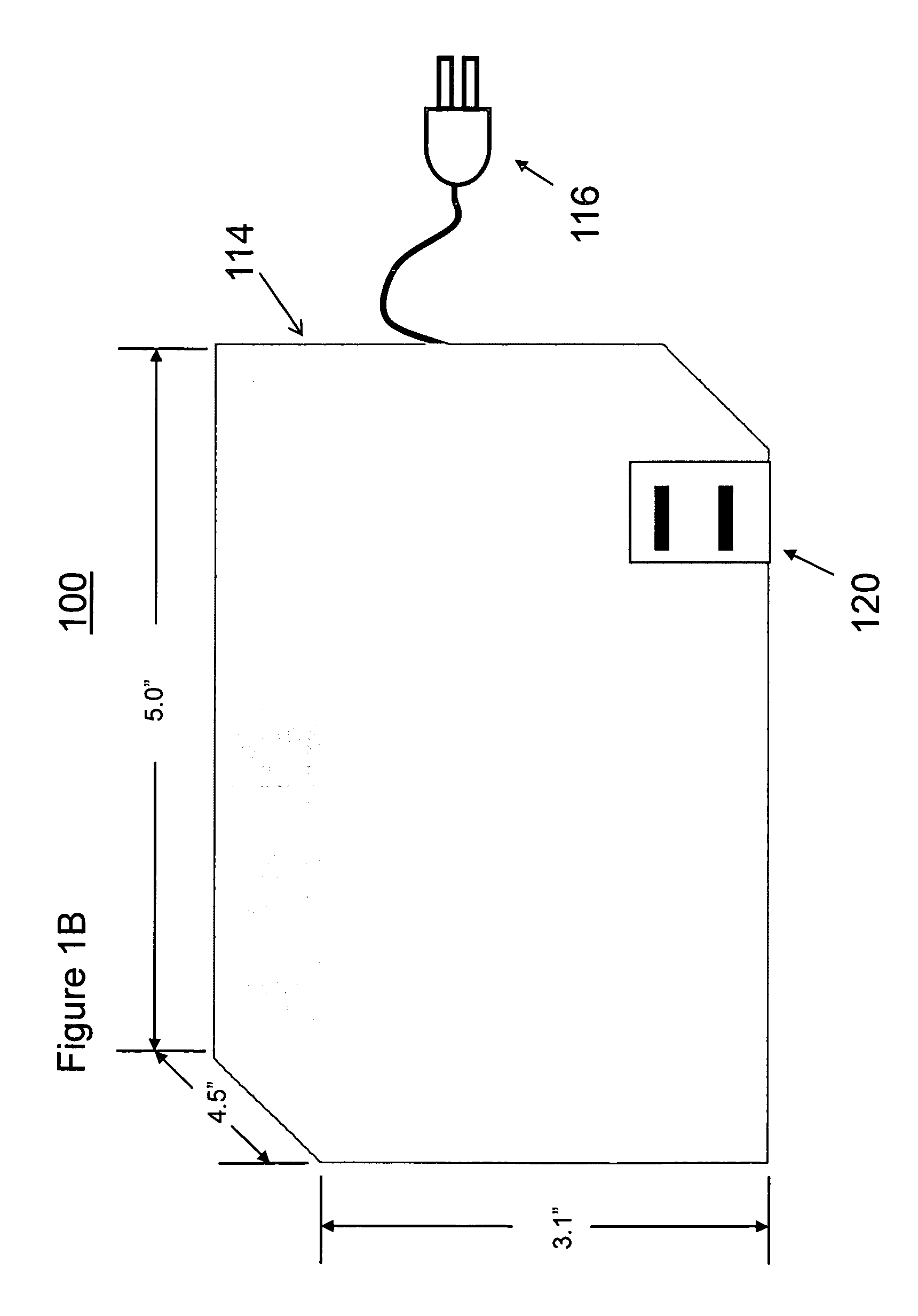
[0024]A system 100 of FIG. 1A comprises a rechargeable battery 102, a charging circuit 104, preferably a trickle-charging circuit, a relay 106, a DC to AC inverter 108, and a timing circuit 110 to optimize a voltage output of the system based on current battery voltage and a desired time period for the voltage output. The system 100 can further comprise an AC receptacle 112 to provide a connection to an appliance to be powered. The system 100 is encased inside a durable housing 114 and can further include a connection means 116, such as an AC cord and plug, to provide a connection to a main power source.

[0025]The rechargeable battery 102 can be a sealed lead acid battery, a nickel metal hydride battery, a lithium ion battery, or any battery capable of being recharged. The battery 102 can be continuously fully charged by a trickle-charging circuit 104, which also can recharge the battery 102 within a specific time period, such as, for example, 12 to 24 hours, by connecting the system...


PUM


Abstract

A substantially uninterruptible backup power system to provide power to common household appliances comprises a rechargeable battery, a trickle-charging circuit to keep the battery fully charged at all times from the receptacle power, a DC to AC inverter to supply standard AC line voltage from the battery to the lamp, a relay switch, controlled by main power voltage, to switch to the backup system when main power fails, and a timing circuit to optimize a voltage output of the system based on current battery voltage and a desired time period for the voltage output. The system can be set to operate only when the appliance is turned on, which optimizes the current and power required to provide backup power to the appliance for a maximum period of time.

Description

CLAIM TO PRIORITY[0001]This application claims the benefit of our co-pending U.S. Provisional application entitled “EMERGENCY BACK-UP POWER SYSTEM,” which was filed on Jun. 4, 2007 and was assigned Ser. No. 60 / 941,744, which is incorporated by reference herein.BACKGROUND[0002]1. Field of the Invention[0003]Embodiments of the present invention generally relate to back-up power systems, and, in particular, to a system for providing back-up battery operated power to an appliance in the event of a power failure.[0004]2. Description of the Related Art[0005]Power outages during times of floods, high wind, wildfires, ice and snow storms, and other natural disasters are relatively common even in the U.S. When power fails, one of the most disturbing consequences is being left in the dark, especially for the elderly or families with small children. To overcome this problem, multiple systems have been developed in the general area of uninterruptible power sources, emergency lighting, and home ...

Claims


Application Information

Patent Timeline
Patent Type & Authority Applications(United States)
IPC IPC(8): H02J9/00
CPCH02J9/065
Inventor SHAKESPEARE, WALTER JEFFREYCROMPTON, CLARENCE WILLIAM
Owner ELECTRIKUS
Learn More