
Cooling system having inlet control and outlet regulation

a technology of inlet control and outlet regulation, applied in the field of cooling systems, can solve the problems of complex calculations, limited operation of the engine, and inability to control the bypass valve in time,

Active Publication Date: 2008-12-04
CATERPILLAR INC
View PDF36 Cites 16 Cited by
  • Summary
  • Abstract
  • Description
  • Claims
  • Application Information

AI Technical Summary

Problems solved by technology

That is, the engine may have a maximum temperature and a most efficient operating temperature range, and operation of the engine may be limited by the ability of the associated exchangers to maintain the engine's temperatures below the maximum limit and within the optimum range.
Although the coolant circuit of the '875 patent may help to maintain desired coolant temperatures, it may be complex and limited.
Specifically, the coolant circuit utilizes multiple temperatures sensors and requires complex calculations to control the bypass valve.
The multiple sensors increase hardware cost and complexity, while the multiple inputs and calculations increases control difficulty.
Further, because control of the bypass valve is based primarily on engine outlet temperature, the inlet temperature experienced by the engine and having the greatest effect on engine operation may be insufficiently controlled.
Further, the coolant circuit of the '875 patent may be inapplicable to an engine system having dual coolant circuits interrelated by way of primary and secondary aftercoolers.

Method used


Image

  • Cooling system having inlet control and outlet regulation
  • Cooling system having inlet control and outlet regulation
  • Cooling system having inlet control and outlet regulation

Examples


Embodiment Construction

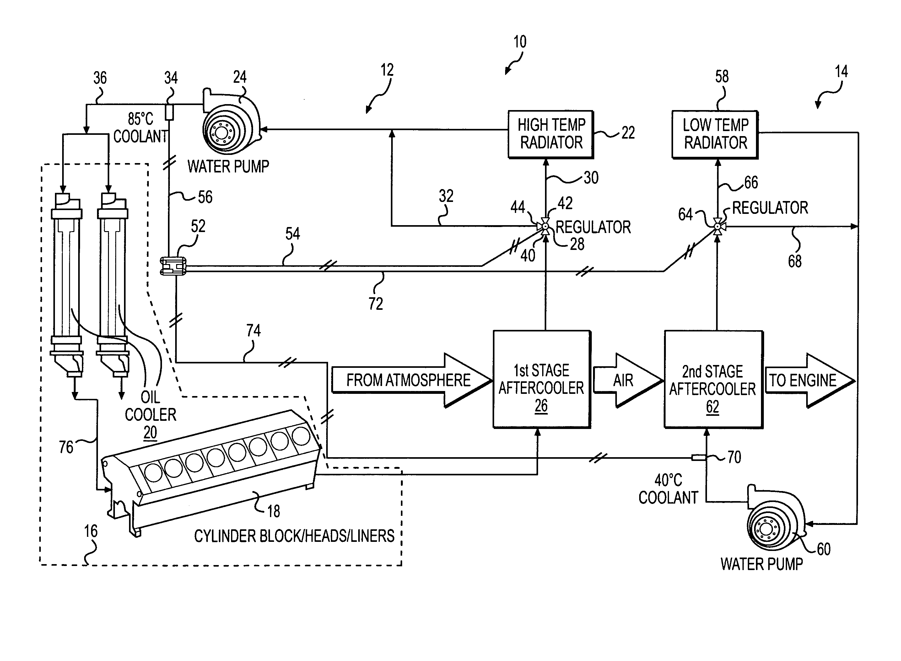
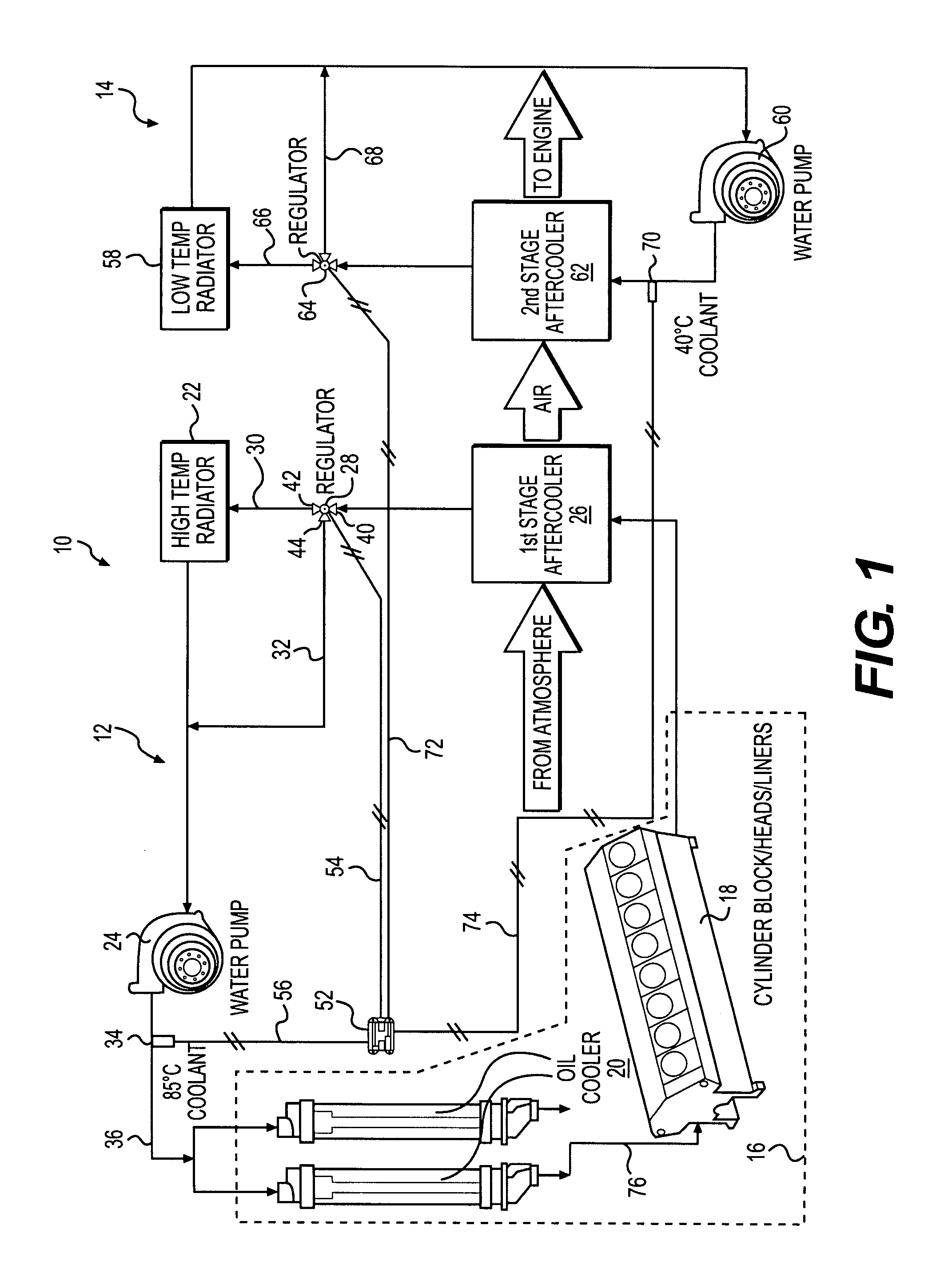
[0012]FIG. 1 illustrates a cooling system 10. Cooling system 10 may include a high temperature circuit 12 and a low temperature circuit 14. High temperature circuit 12 may regulate coolant flow from a heat source 16 based on a coolant inlet temperature of the heat source 16. Low temperature circuit 14 may regulate coolant flow from an aftercooler 62 based on a coolant inlet temperature of the aftercooler 62.

[0013]Heat source 16 may embody an engine having multiple components that cooperate to combust a fuel / air mixture and produce a power output. For example, heat source 16 may be a diesel engine, a gasoline engine, or a gaseous fuel-powered engine having an engine block 18 that defines a plurality of cylinders, a piston (not shown) slidably disposed within each cylinder, and a cylinder head associated with each cylinder. Heat source 16 may draw the fuel / air mixture into each cylinder, compress the mixture with the piston, and ignite the mixture to produce a combination of power, he...


PUM


Abstract

A cooling system is disclosed. The cooling system may have a heat source, a heat exchanger, and a coolant pump located between the heat exchanger and the heat source to direct coolant from the heat exchanger to the heat source. The cooling system may also have a valve located between the heat source and the heat exchanger. The valve may be movable to vary a rate of coolant flow through the heat exchanger and around the heat exchanger to the coolant pump. The cooling system may further have a sensor located at an inlet of the heat source to generate a signal indicative of coolant temperature at the inlet, and a controller in communication with the valve and the sensor. The controller may be configured to move the valve based on the temperature of the coolant at only the inlet of the heat source.

Description

TECHNICAL FIELD[0001]The present disclosure relates generally to a cooling system and, more particularly, to a cooling system that regulates a coolant outlet flow from a heat producing device based on a coolant inlet temperature of the heat producing device.BACKGROUND[0002]Engines, including diesel engines, gasoline engines, and gaseous fuel-powered engines are used to generate a mechanical, hydraulic, or electrical power output. In order to accomplish this power generation, an engine typically combusts a fuel / air mixture. This combustion process generates large amounts of heat and, in order to ensure proper and efficient operation of the engine, a cooling system is required to cool fluids directed into or out of the engine.[0003]An internal combustion engine is generally fluidly connected to several different liquid-to-air and / or air-to air heat exchangers to cool both liquids and gases circulated throughout the engine. These heat exchangers are often located close together and / or ...

Claims


Application Information

Patent Timeline
Patent Type & Authority Applications(United States)
IPC IPC(8): F01P7/14
CPCF01P7/165F01P2023/08F01P2025/30F01P2031/30F01P2037/02
Inventor HARRIS, JAMES WALLACERAMM, MICHAEL PATRICKPREWETT, JEFFERY LYNN
Owner CATERPILLAR INC
Learn More