Image processing apparatus, method thereof, and program

Inactive Publication Date: 2008-11-20
SONY CORP
View PDF5 Cites 0 Cited by
  • Summary
  • Abstract
  • Description
  • Claims
  • Application Information

AI Technical Summary

Benefits of technology

[0016]Hence, if the accelerator 3 is assigned to perform all accelerator-capable processing, its load increases conversely, which then increases time required for the CPU 1 to poll the accelerator 3, thereby making it likely to increase the total cycle numbers compared with cases where the CPU 1 alone is used.
[0020]As shown in FIG. 2, as understood from a comparison between the computation execution period T1 of the CPU and the computation execution period T3 of the accelerator, since the accelerator has a high computation load, the CPU is polling the accelerator, thereby increasing the period T2 during which the CPU is idling.
[0021]As a result, the efficiency of the paralleling is lowered, and the total cycle numbers increase even if the accelerator is used.
[0034]According to embodiments of the present invention, highly efficient parallel processing in a plurality of processors may be realized.

Problems solved by technology

However, amid the diversified image decompression / compression methods, the techniques with dedicated circuit encounter difficulties in flexibly coping with such methods.

Method used


Image

  • Image processing apparatus, method thereof, and program
  • Image processing apparatus, method thereof, and program
  • Image processing apparatus, method thereof, and program

Examples


Embodiment Construction

[0054]An embodiment of the present invention will now be described with reference to the drawings.

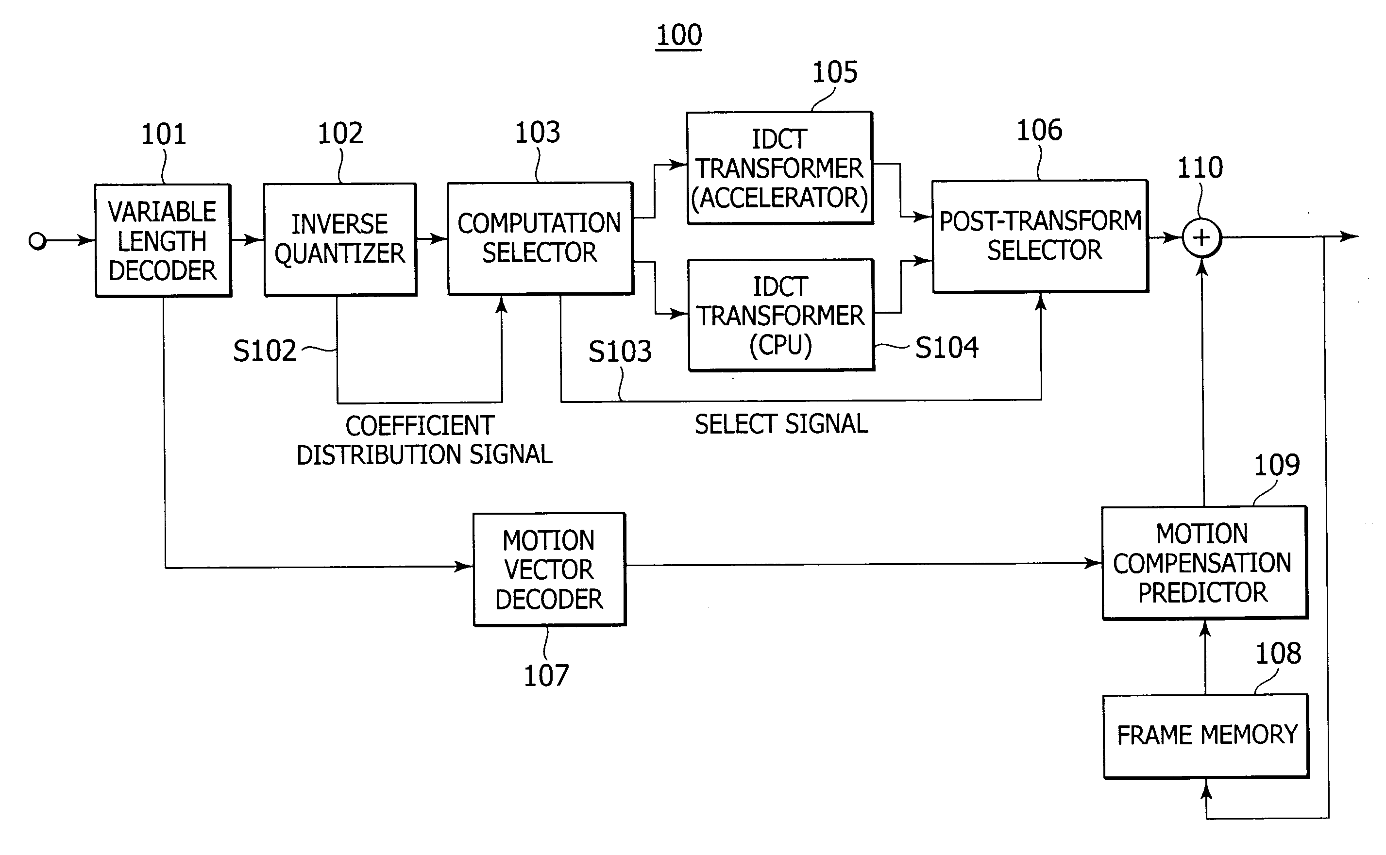
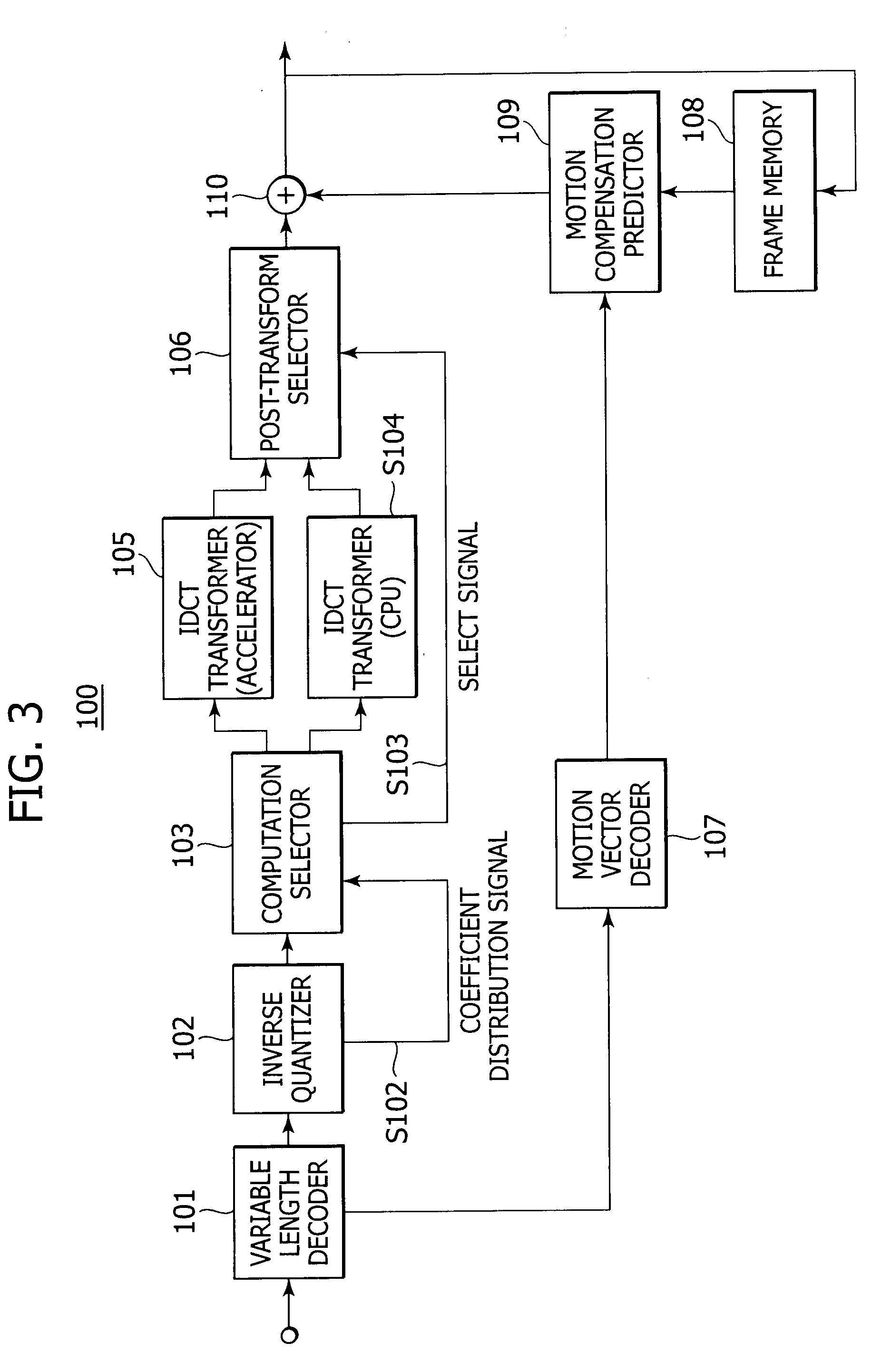
[0055]FIG. 3 is a block diagram showing a configuration of an image processing apparatus according to an embodiment of the present invention.

[0056]This image processing apparatus 100 has, as shown in FIG. 3, a variable length decoder 101, an inverse quantizer 102, a computation selector 103, a first IDCT transformer (Inverse Discrete Cosine Transformer) 104 as a first inverse orthogonal transformer (processor: a CPU), a second IDCT transformer (accelerator) 105 being a second processor as a second inverse orthogonal transformer, a post-transform selector 106, a motion vector decoder 107, a frame memory 108, a motion compensation predictor 109, and an adder 110.

[0057]In the image processing apparatus 100 according to the present embodiment, when the second IDCT transformer (accelerator) 105 is caused to perform IDCT processing in MPEG, it is configured to avoid transfer of data not requi...


PUM


Abstract

An image processing apparatus that divides an input image signal into blocks, inversely quantizes image-compressed information, and decodes the image-compressed information by performing an inverse orthogonal transformation. The image processing apparatus includes a first inverse orthogonal transformer capable of performing inverse orthogonal transform processing on inversely quantized coefficient data and capable of performing processing other than the inverse orthogonal transform processing, a second inverse orthogonal transformer capable of performing the inverse orthogonal transform processing on the inversely quantized coefficient data, a decoder decoding quantized and coded transform coefficients, an inverse-quantizer inversely quantizing decoded transform coefficients decoded by the decoder, and indicating distribution information of significant coefficient data as flag information for each block for inverse quantization processing during the inverse quantization, and a selector selectively outputting coefficient data inversely quantized by the inverse quantizer to the first inverse orthogonal transformer or the second inverse orthogonal transformer.

Description

BACKGROUND OF THE INVENTION[0001]1. Field of the Invention[0002]The present invention relates to an image processing apparatus, a method thereof, and a program, all for processing digital images.[0003]2. Description of Related Art[0004]In recent years, apparatuses compliant with Moving Picture Experts Group (MPEG) type have gained popularity in both information distribution side, such as broadcasting stations and information receiving side, such as at ordinary homes. The MPEG type handles image information by digitizing it, and during handling such information, for the purposes of highly efficient transmission and storage of information, performs compression based on an orthogonal transform such as a Discrete Cosine Transform (DCT) and motion compensation, by utilizing redundancies unique to the image information.[0005]Particularly, MPEG2 (ISO / IEC 13818-2) is defined as a general-purpose image encoding type, and is presently used extensively for both professional and consumer applic...

Claims


Application Information

Patent Timeline
IPC IPC(8): G06K9/36G06T1/20H03M7/30H04N1/41H04N19/102H04N19/12H04N19/127H04N19/134H04N19/136H04N19/159H04N19/196H04N19/423H04N19/433H04N19/436H04N19/44H04N19/503H04N19/513H04N19/577H04N19/60H04N19/61H04N19/625H04N19/91
CPCH04N19/159H04N19/176H04N19/46H04N19/122H04N19/436H04N19/127H04N19/14H04N19/44H04N19/61
Inventor EBIHARA, MASAKAZUNABESAKO, HIDEKI
Owner SONY CORP
Why Eureka
Try Eureka