Concentrated winding machine with magnetic slot wedges

a winding machine and magnetic technology, applied in the field of electric machines, can solve the problems of reducing the slot fill, reducing the stiffness of the stator, and weakening the mechanical structure of the stator

Inactive Publication Date: 2008-11-20
GM GLOBAL TECH OPERATIONS LLC
View PDF15 Cites 6 Cited by
  • Summary
  • Abstract
  • Description
  • Claims
  • Application Information

AI Technical Summary

Benefits of technology

[0011]A method is provided for improving operational characteristics of a concentrated winding machine. The method comprises fabricating a fixed-tooth stator that has stator teeth, the stator teeth defining stator slots and slot openings between adjacent stator teeth, the fixed-tooth stator not allowing for relative movement between adjacent stator teeth. The method further comprises inserting magnetic wedges between adjacent stator teeth to close the slot openings.

Problems solved by technology

A disadvantage to using the plastic bobbin 640 as a slot liner is that it reduces the slot fill.
Although paper insulation slot liners are thinner than plastic slot liners, paper insulation slot liners cannot be used in conventional segmented stator construction because bobbin style winding is not possible as the paper is often twisted or cut as the coil is wound around the paper.
However, a disadvantage to the method of stator construction illustrated in FIG. 3 is that it weakens the stator mechanical structure and lowers its stiffness.
Therefore, compared to the segmented stator construction method illustrated by FIG. 1, this method is more susceptible to undesirable vibration and noise.

Method used


Image

  • Concentrated winding machine with magnetic slot wedges
  • Concentrated winding machine with magnetic slot wedges
  • Concentrated winding machine with magnetic slot wedges

Examples


Embodiment Construction

[0026]The following detailed description is merely exemplary in nature and is not intended to limit the invention or the application and uses of the invention. Furthermore, there is no intention to be bound by any expressed or implied theory presented in the preceding technical field, background, brief summary, or the following detailed description.

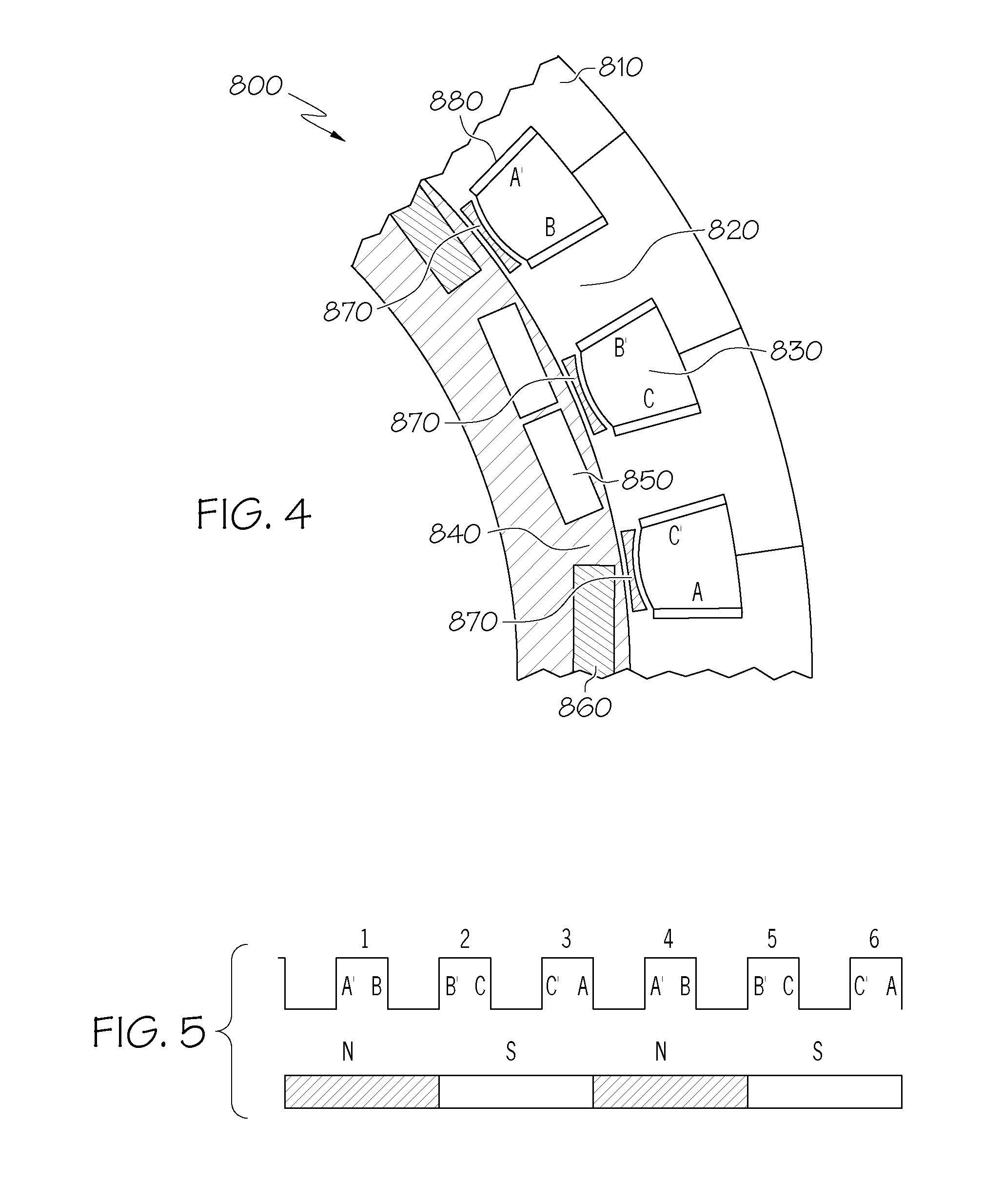
[0027]FIG. 4 is a sectional diagram illustrating the arrangement of the stator slots and rotor poles in a portion 800 of a concentrated winding machine in accordance with an example embodiment. The portion 800 illustrated in FIG. 4 has a periodicity of 8, that is, only ⅛th of the complete geometry is shown in the diagram.

[0028]In portion 800, fixed-tooth stator segments 810 each have a stator tooth 820, where stator slots 830 are defined between adjacent stator teeth 820. Also shown in portion 800 are a rotor 840, north rotor poles 850, and south rotor poles 860. In total, there are twenty-four stator slots 830 and sixteen rotor poles 850...


PUM

PropertyMeasurementUnit
peak-to-peak cogging torqueaaaaaaaaaa
conductiveaaaaaaaaaa
permeabilityaaaaaaaaaa

Abstract

Methods and apparatus are provided for improving operational characteristics of a concentrated winding machine. According to an example embodiment, a method comprises fabricating a magnetic slot wedge that is adapted to be joined to a first stator tooth and a second stator tooth, the first and second stator tooth part of a fixed-tooth stator that does not allow relative movement between the first stator tooth and the second stator tooth.

Description

CROSS REFERENCE TO RELATED APPLICATIONS[0001]This disclosure is related to U.S. patent application having attorney docket no. GP-308954-PTH-CD, entitled “Concentrated Winding Machine with Magnetic Slot Wedges,” which is incorporated by reference in its entirety.TECHNICAL FIELD[0002]This disclosure relates generally to electrical machines, and more particularly relates to concentrated winding machines.BACKGROUND OF THE INVENTION[0003]An electrical machine may have distributed windings or concentrated windings, the difference between these windings being well known to those of ordinary skill. In a concentrated winding machine, a stator may be constructed in segments, which are then connected to form the entire stator. This is illustrated in FIG. 1, which is a sectional diagram illustrating a conventional segmented stator 500 that is composed of a number of stator segments 510. Each stator segment includes an integral tooth 512 and teeth tips 515. The teeth 512 define stator slots 520 ...

Claims


Application Information

Patent Timeline
Patent Type & Authority Applications(United States)
IPC IPC(8): H02K15/02H02K15/085
CPCH02K3/493H02K3/522Y10T29/49075H02K15/066Y10T29/49009H02K15/0018
Inventor RAHMAN, KHWAJA M.KAISER, EWARD L.LABA, MATTHEW D.
Owner GM GLOBAL TECH OPERATIONS LLC
Why Eureka
Try Eureka