
Strut for Locking the Engine of an Aircraft

a technology for aircraft engines and struts, which is applied in the direction of power plant construction, aircraft power plants, transportation and packaging, etc., can solve the problems of loss in the performance level of aircraft, loss of relative consequence, and large height of engine mounts

Inactive Publication Date: 2008-11-06
AIRBUS OPERATIONS (SAS)
View PDF7 Cites 22 Cited by
  • Summary
  • Abstract
  • Description
  • Claims
  • Application Information

AI Technical Summary

Benefits of technology

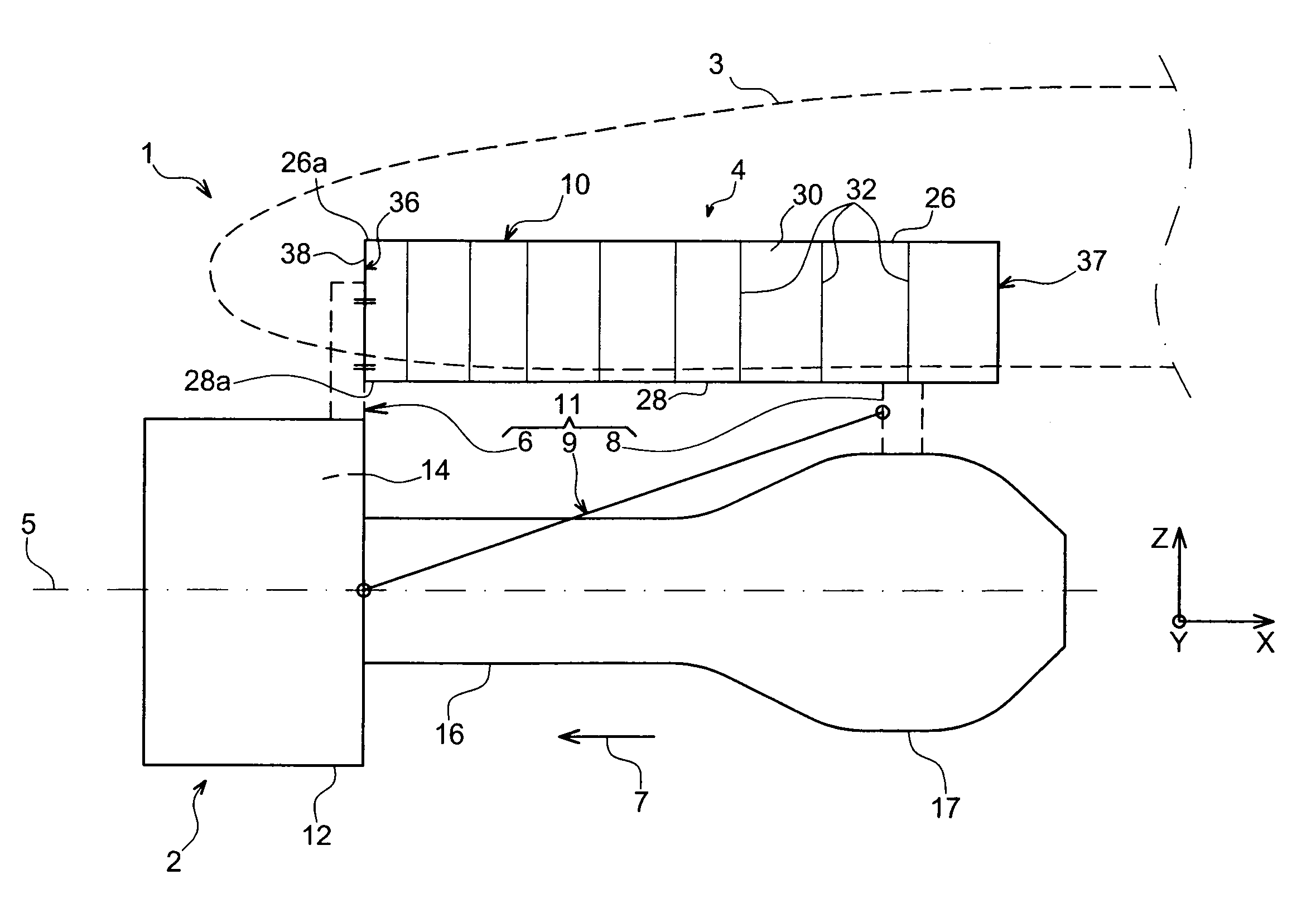
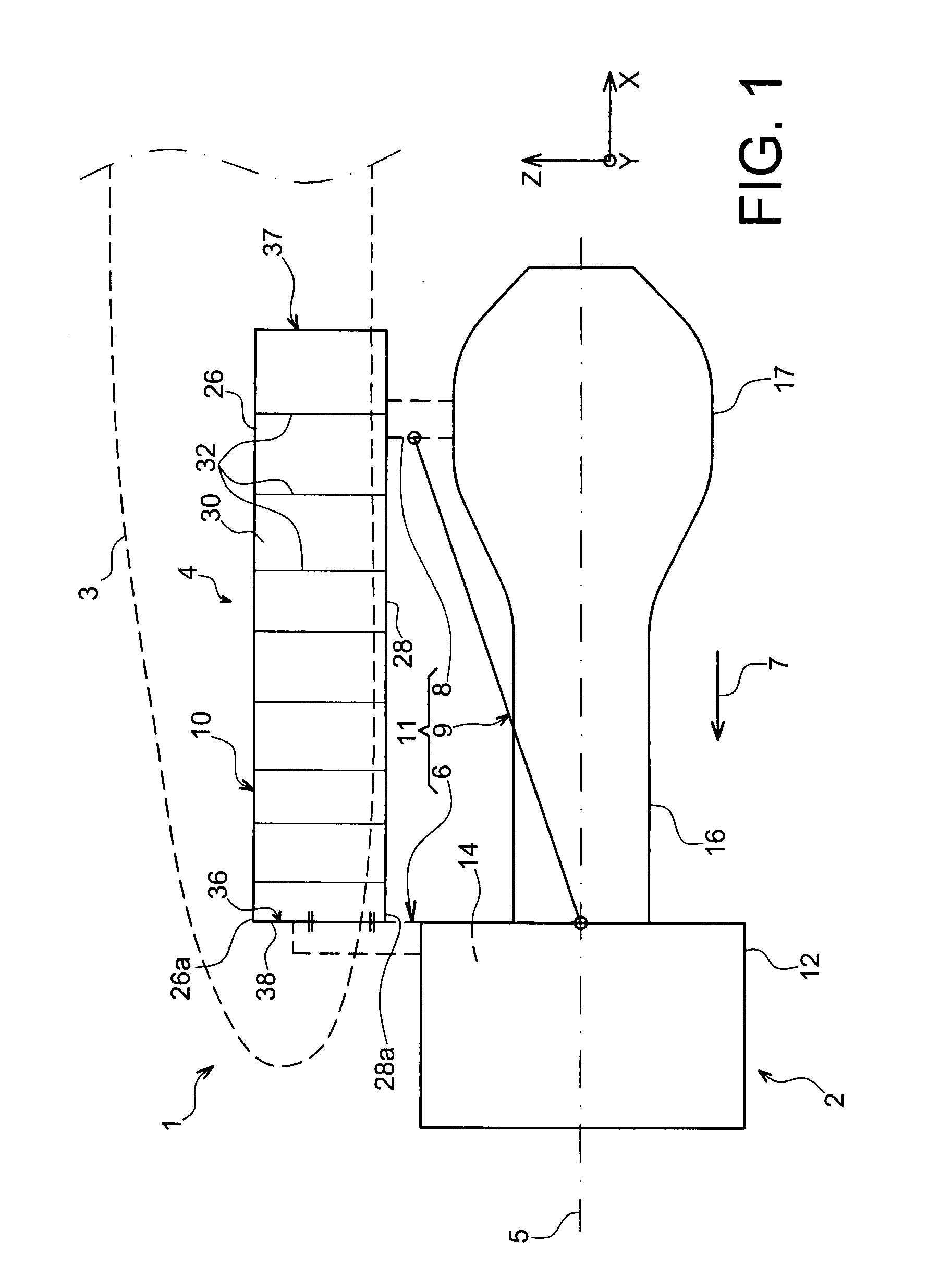
[0017]Therefore said configuration clearly generates more space below the lower spar of the box, and hence generates a decrease in aerodynamic disturbance over the forward engine attachment. For an attachment body of same size, the generated drag is therefore advantageously lower than previously encountered.
[0018]Additionally, again in the preferred case when the engine mount is to be used to suspend an engine below the aircraft wing, the fact that the attachment body of the forward attachment is raised, means that that the ground clearance under the associated engine can be increased.
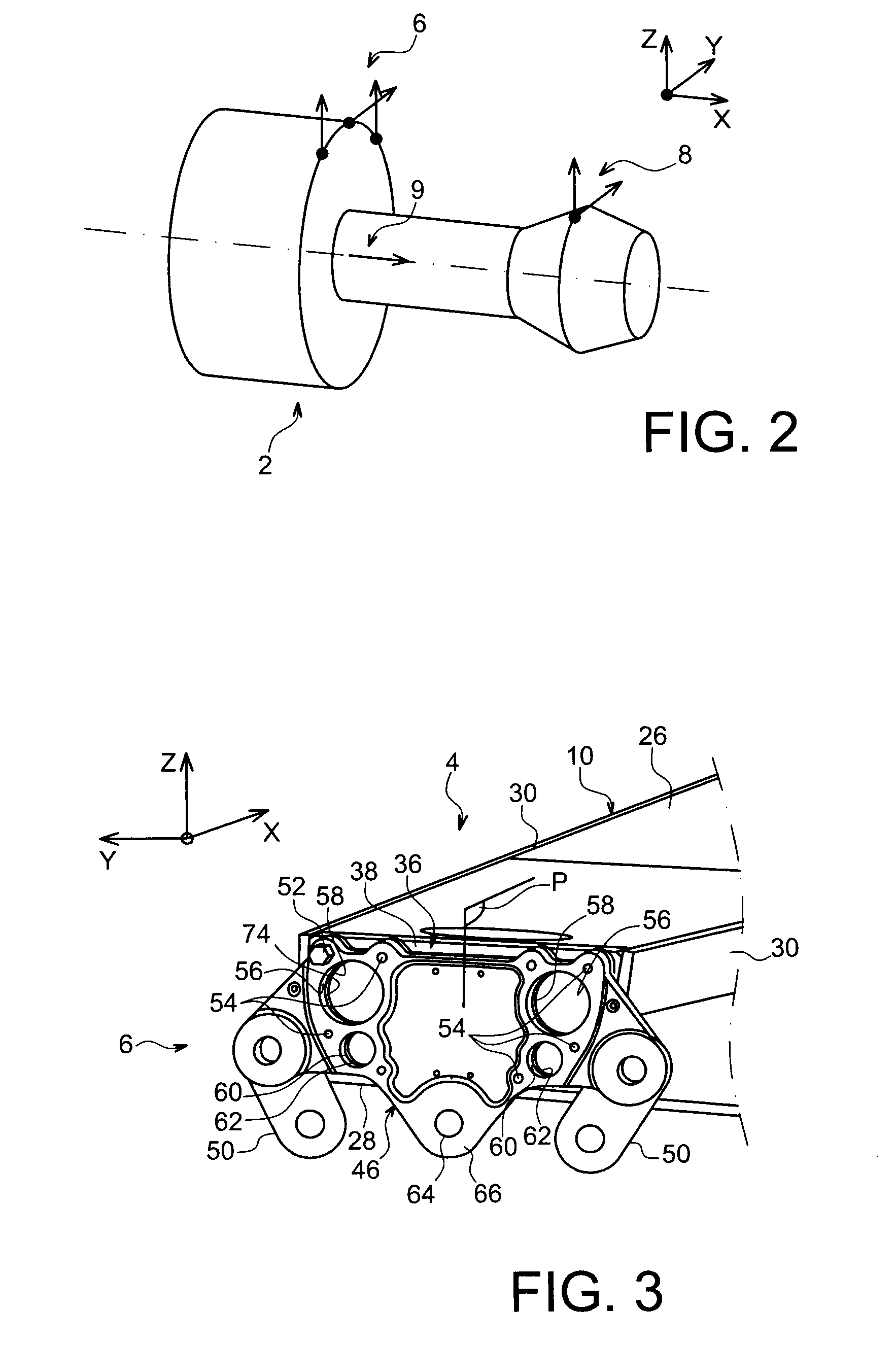
[0022]In addition, the forward engine attachment preferably comprises a plurality of tension bolts ensuring the fixing of the attachment body onto the forward closure rib, these bolts making it possible in particular to limit the size of the shear pin(s) used.
[0033]As a result, owing to the special arrangement of this contact surface belonging to the forward closure rib of the box, which can therefore be oriented substantially vertically for example, i.e. in a plane defined by the transverse and vertical directions of the engine mount, or slightly at an angle relative to the vertical while preferably remaining parallel to the transverse direction, there is advantageously obtained an improvement in accessibility for maneuvering the securing members intended to ensure assembly of the attachment body onto the rigid structure. It is effectively provided that this body is advantageously fixed to a forward surface of the forward closure rib of the box-shaped rigid structure. Since the entire rigid structure is positioned towards the aft relative to the securing interface, the operator therefore has the benefit of a free space forward of this interface which largely facilitates handling of the different parts used to achieve securing of the attachment body.
[0036]Evidently, it is noted that the pre-positioning of the engine relative to the rigid structure is made with sufficient accuracy so that the pin with convex head is able successively to enter the first then the second primary orifice, or conversely, by generating progressive correction of alignment translating as a relative movement between the engine and the rigid structure, despite the substantial vertical load associated with the engine.
[0042]Therefore the positioning of these support pins, also called indexing supports, ensures the holding of the engine slightly below its final position with respect to the engine mount, this position being fully appropriate for subsequent insertion of the centering pin with convex head in the primary orifices.

Problems solved by technology

This arrangement has a non-negligible disadvantage i.e. the entirety of the attachment body projects downwardly from the box, causing the rigid structure to be positioned well above the engine fan case, thereby leading to an engine mount of great height, which is substantially penalising with regard to aerodynamic drag, and evidently translates as a loss in the performance level of the aircraft.
In this respect, it is noted that such loss is of relative consequence owing to the large dimensions of the attachment body, imposed by the need to ensure the transmitting of engine-derived loads in the direction of the rigid structure of the engine mount.

Method used


Image

  • Strut for Locking the Engine of an Aircraft
  • Strut for Locking the Engine of an Aircraft
  • Strut for Locking the Engine of an Aircraft

Examples


Embodiment Construction

[0013]The purpose of the invention is therefore to propose an aircraft engine mount which overcomes the above-mentioned drawback connected with prior art embodiments, and also to present an engine assembly provided with said mount.

[0014]A further purpose of the invention is to propose a method to mount an engine onto the rigid structure of this engine mount.

[0015]For this purpose, the subject-matter of the invention is an aircraft engine mount comprising a rigid structure forming a box closed at its forward end by a forward closure rib, and an engine mounting system assembled fixedly on the rigid structure and notably comprising a forward engine attachment provided with an attachment body mounted fixedly on the rigid structure. According to the invention, the attachment body of the forward engine attachment lies against a forward surface of the forward closure rib of the box. In addition, the forward engine attachment comprises at least one shear pin passing at least in part through...


PUM


Abstract

An engine mount for an aircraft engine. The engine mount includes a rigid structure forming a box closed at its forward end by a forward closure rib, and a mounting system including a forward engine attachment having an attachment body fixedly mounted on the rigid structure. The attachment body lies against a forward surface, and the engine mount includes at least one shear pin passing at least in part through the attachment body and forward closure rib.

Description

TECHNICAL AREA[0001]The present invention generally relates to an aircraft engine assembly, of the type comprising an engine and a pylon to secure the engine, equipped in particular with an engine mounting system which comprises a plurality of engine attachments and is positioned between a rigid structure of the pylon and the engine.[0002]The invention also relates to said pylon for an aircraft engine.[0003]The invention can be used on any type of aircraft equipped with turbojet engines for example or turboprop engines.[0004]This securing pylon, also called <<EMS>> (Engine Mounting Structure), permits the suspending of a turbojet engine below the wing of an aircraft for example, or the mounting of this turbojet engine above this same wing.STATE OF THE PRIOR ART[0005]Said engine mount is intended to form a connecting interface between an engine such as a turbojet engine and an aircraft wing. It permits the loads generated by its associated turbojet engine to be transferre...

Claims


Application Information

Patent Timeline
IPC IPC(8): B64D27/00
CPCB64D27/26B64D2027/266B64D27/40B64D27/404
Inventor LAFONT, LAURENTJOURNADE, FREDERICRENAUD, ERIC
Owner AIRBUS OPERATIONS (SAS)
Learn More