Eureka AIR delivers breakthrough ideas for toughest innovation challenges, trusted by R&D personnel around the world.

Fluid Conduit with Layered and Partial Covering Material Thereon

a technology of flue gas conduit and layered material, which is applied in the direction of sewage draining, filtration separation, separation process, etc., can solve the problems of lint and fuzz, the septic tank generally available does not effectively provide for the removal, and the solids that pass through the tank neither cool nor make contact at a slow enough pace to separate from the water, etc., to achieve the effect of reducing the amount of effluent, reducing the amount of solid

Active Publication Date: 2008-11-06
PRESBY PLASTICS INC
View PDF23 Cites 9 Cited by
  • Summary
  • Abstract
  • Description
  • Claims
  • Application Information

AI Technical Summary

Benefits of technology

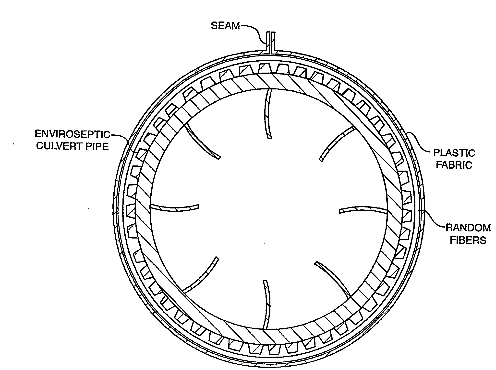
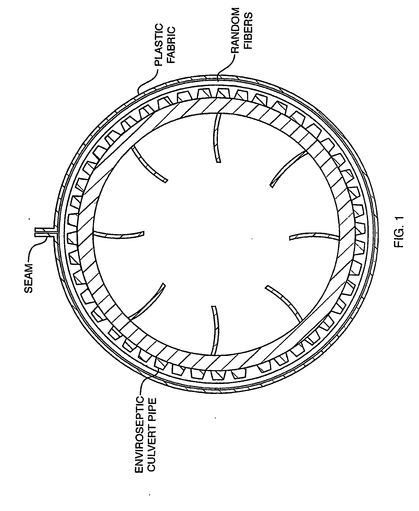
[0056]Through testing of the Enviro-Septic® wastewater treatment system, surprisingly Applicant / Inventor hereof has learned that by adding a dense layer of geo-textile fabric in the lower section of the pipe (covering a portion of the circumference of the pipe (C)—such portion being preferably less than one-half of the pipe circumference (<½C) and placed between the pipe outer surface and a layer of coarse random fibers, Applicant was able to get the bacteria to grow very quickly. Such result forces the system to generate bacteria more quickly and thereby causing the system performance to be enhanced in quality of performance and in the speed of performance—speed of performance was increased over prior art methods by a substantial of amount.
[0057]The extra layer of dense fabric not only helps to treat the effluent better but also helps to extend the life of the outer layer of fabric wrapped around the pipe. In the prior reference patents of Applicant, referred to herein on occasion as the original Enviro-Septic® pipe the outer layer of fabric eventually gets a buildup of sludge that escapes through the holes in the pipe settling on the inside of the outer layer of fabric. By adding the new layer of dense fabric, the sludge is trapped on this layer thereby protecting the outer layer of fabric from this sludge. At the time of initial startup this new dense fabric layer will screen the effluent better, thereby causing the effluent to travel the whole length of the pipe quickly and uniformly. As the effluent passes through the dense fabric layer, the bacteria will reach a long-term acceptance rate faster and the effluent will overflow or pond above the upper edges of the dense layer eventually overflowing down and into the coarse random fibers and passing through the outer layer of fabric. By allowing the effluent to travel the whole length of the pipe it results in the spreading of the loading throughout, —a process that allows more air and better bacterial growth and action. during this process a second biomat forms on the inner surface of the outer fabric and now becomes the treatment surface. It is not clogged by the sludge because it is being protected by the dense layer of fabric next to the pipe.
[0058]This dense layer of fabric does not stop the penetration of effluent. It slows the effluent down and filters it better, allowing the bacteria to grow sooner and in greater numbers.
[0059]This extra layer of dense fabric will allow for a longer life expectance than is now achieved or even expected from the standard and Patented Enviro-Septic® system. It will also allow the system to reach its peak environmental performance in a much shorter period of time.
[0061]It has been discovered surprisingly that incorporating—i.e., adding a plurality (from 2 to “n” dense layers) of dense layer of geo-textile fabric in the lower section of the pipe wherein each of the ones of the plurality of dense layers is designed for covering a portion of the circumference of the pipe (C). Each of the dense layers beginning with a first dense layer—the layer which is in contact with the outer surface of the pipe—being preferably substantially about equal to about ½ of 1 / n th of the pipe circumference (C) and placed between the pipe outer surface and a layer of coarse random fibers. The second (2nd) dense layer would be placed onto or i.e., over the coarse random fiber layer (note that all of the coarse random fiber layers may be of size to cover the pipe circumference or they may be of a dimension to cover a portion of the pipe greater than the dense layer inwardly directed and perhaps less than the dense layer contacting the outwardly directed surface of the 2nd dense layer. This relationship will be applied to each of the successive dense layers to the final n th dense layer. It is clear that each of the course fiber layers may completely encircle the pipe because the flow through of the fluid is minimally effected by the material of the course fiber layers. Applicant was able to get the bacteria to grow very quickly. Such result forces the system to generate bacteria more quickly and thereby causing the system performance to be enhanced in quality of performance and in the speed of performance—speed of performance was increased over prior art methods by a substantial of amount.

Problems solved by technology

The major problem with the septic tank is that the suspended solids in passing through the tank neither cool nor make contact at a slow enough pace to separate from the water.
Lint and fuzz has also been an ongoing problem for the septic tank to control.
This material stays suspended in the septic tank liquid and normally passes through, remaining suspended in the effluent which subsequently also causes problems in the leach system connected with the septic tank.
Septic tanks generally available do not effectively provide for the removal, in a manner which does not effect the cost and the performance characteristics of the septic treatment system. of suspended solids that are typically found in septic tank liquid.
A leach field, for example, is adversely effected because the suspended solids will clog receiving layer and also adversely affect the absorption characteristics of the leach bed.
Filtration creates an additional set of problems.
The filters are expensive and are costly to maintain.
There is nothing currently available which satisfies these needs and objectives.
Additionally none are as effective and as efficient as the instant improved conduit system.
The Gonczy patent does not disclose the use of multilayer fabrics of varying deniers and does not disclose the liquid permeability of the multilayer blanket.
None of them are as effective and as efficient as the install combination of multilayered fabric and corrugated pipe combination for use in the management of effluent drainage systems.

Method used


Image

  • Fluid Conduit with Layered and Partial Covering Material Thereon
  • Fluid Conduit with Layered and Partial Covering Material Thereon
  • Fluid Conduit with Layered and Partial Covering Material Thereon

Examples


Embodiment Construction

[0077]The following is a description of the preferred embodiment of the invention. It is clear that there may be variations in the size and the shape of the apparatus, in the materials used in the construction and in the orientation of the components. However, the main features are consistent and are;

[0078]1) Multiple layers of fabric rather than screens;

[0079]2) Fabric layers of varying deniers and / or thickness;

[0080]3) Useful in wrapping smooth-walled and corrugated plastic pipe;

[0081]4) With the selection of fabric and fabric denier, specific fluid treatment objectives can be met;

[0082]5) The multilayer fabric provides boundaries / interfaces and regions within which specifically chosen bacteria, chemicals, microbes and the like may be introduced to facilitate the biodegradation of specifically chosen undesirable materials; and

[0083]6) Improve performance over the currently known leach fields.

[0084]7) One of the most particular features of this newly disclosed invention is now desc...


PUM

PropertyMeasurementUnit
circumferenceaaaaaaaaaa
shapeaaaaaaaaaa
surface areaaaaaaaaaaa

Abstract

A fluid conduit with layered and partial covering material thereon. The fluid conduit may be of many forms and types and attached thereto and configured thereon covering material, in partial form and a selected number of layers. The covering of fluid conduit / conductors resulting in the creation of a novel and very effective, in functionality, of a fluid conduit / conductive system, such as a septic pipe of smooth wall, of corrugated form, of any form of cross sectional configuration including circular, elliptical, rectangular, triangular or any other geometric shape any of which will and can provide for the flow of a fluid of forms such as septic flow fluid and the like. Included herein as a part of the invention is fluid conduits produced by the means and methods of this invention. Substantially, the fluid conduit system having incorporated therein and thereon the form and layers of covering created as a consequence of the means and method of configuring such conduit included as a feature of the invention. Used herein is a multilayer fabric of varying deniers for the processing and treatment of fluids which must be treated to remove materials so that the resultant treated fluid may be reused and / or returned to the earth and particularly to the water table. More particularly the multilayer fabric, each layer being of selected denier, is used in combination with conduit in a drainage field or leaching system usually associated with a septic tank or septic system. Most particularly the multilayer fabric of varying deniers is wrapped around corrugated plastic pipe of the type well known in the field of drainage or leaching fields. At least one of the multilayer fabric layers is formed from an unstructured assemblage of fibers. The unstructured assemblage of fibers are supported by an outer sheeting however it could be made of a grid mesh or additional material choices which in effect will provide for separation between layers. The unstructured assemblage of fibers provides a large surface area whereon consequent biodegradation of the oils, greases and chemicals takes place permitting treated fluid to pass omnidirectionally through the unstructured assemblage of fibers and subsequently leach into the ground. The system generates bacteria more quickly and thereby causing the system performance to be enhanced in quality of performance and in the speed of performance—speed of performance was increased over prior art methods by a substantial of amount.

Description

[0001]This patent application claims the benefit of U.S. Provisional Application No. 60 / 683,994 filed May 24, 2005; U.S. Pat. No. 6,461,078; Issued Oct. 8, 2002 for U.S. Utility patent application: Ser. No. 09 / 524,238; Filed Mar. 13, 2000 entitled as “PLASTIC SEWAGE PIPE” and also the benefit of U.S. Pat. No. 5,954,451; Issued Sep. 21, 1999 for U.S. Utility patent application: Ser. No. 08 / 998,351; Filed Dec. 18, 1997 entitled as “A METHOD AND APPARATUS FOR USING MULTILAYER MATERIAL IN PROCESSING OF SEPTIC EFFLUENT AND WASTE WATER”. The drawing figures, the method of use, the advantages and additional characteristics and the functionality of U.S. Pat. Nos. 6,461,078 and 5,954,451 are included herein as referenced thereto.BACKGROUND OF THE INVENTION[0002]1. Field of the Invention[0003]This invention most generally relates to a fluid conduit with layered and partial covering material thereon and means and method for configuring with covering material, in partial form and layers, a cove...

Claims


Application Information

Patent Timeline
Patent Type & Authority Applications(United States)
IPC IPC(8): F16L11/00
CPCE03F1/002E03F3/06E03F2003/065E03F3/04F16L9/14B01D23/06B01D2201/0415B01D29/23C02F3/2826B01D23/04Y02W10/10B01D29/27B01D29/31C02F3/02B01D39/02B01D39/083B01D2239/065C02F3/288
Inventor PRESBY, DAVID W.
Owner PRESBY PLASTICS INC
Why Eureka
Eureka Blog
Learn More