
Phase change cooled electrical connections for power electronic devices

a technology of electrical connections and power electronic devices, applied in the direction of cooling/ventilation/heating modifications, semiconductor device details, semiconductor/solid-state device details, etc., can solve the problems of heat generation, and thermal management challenges, and achieve excellent, reliable and well-established effects, limiting the overall life and efficiency of components and systems

Inactive Publication Date: 2008-10-30
ROCKWELL AUTOMATION TECH
View PDF10 Cites 14 Cited by
  • Summary
  • Abstract
  • Description
  • Claims
  • Application Information

AI Technical Summary

Benefits of technology

[0003]In a typical power electronic device, heat originates from a range of sources. For example, heat is generated due to conduction and switching losses in the power electronic components themselves. Moreover, the components, which may be disposed in lead frame and similar packaging, or on power substrates or in power modules, are electrically coupled to one another and to external circuitry by means of leads, contact pads, and similar conducting structures, to which other conductors, typically bonded wire or braid is coupled. Wire bonding provides an excellent, reliable and well established solution for channeling power into and from power electronic components, and between such components. However, conduction losses at connection points for such conductors can be sources of heat that can severely limit the overall life and efficiency of the components and the systems.
[0008]The invention allows for a highly flexible design of individual, combined and particularly for a small strategically placed heat dissipation structures in power electronic circuits. The heat dissipation devices themselves may compliment those used on other components, such as on power modules, individual components, and so forth.

Problems solved by technology

Packaging for such devices often leads to challenging thermal management, particularly for extraction of heat from overall circuitry and from specific locations during operation.
For example, heat is generated due to conduction and switching losses in the power electronic components themselves.
However, conduction losses at connection points for such conductors can be sources of heat that can severely limit the overall life and efficiency of the components and the systems.
However, such solutions do not provide localized cooling of hot spots such as connection points.

Method used


Image

  • Phase change cooled electrical connections for power electronic devices
  • Phase change cooled electrical connections for power electronic devices
  • Phase change cooled electrical connections for power electronic devices

Examples


Embodiment Construction

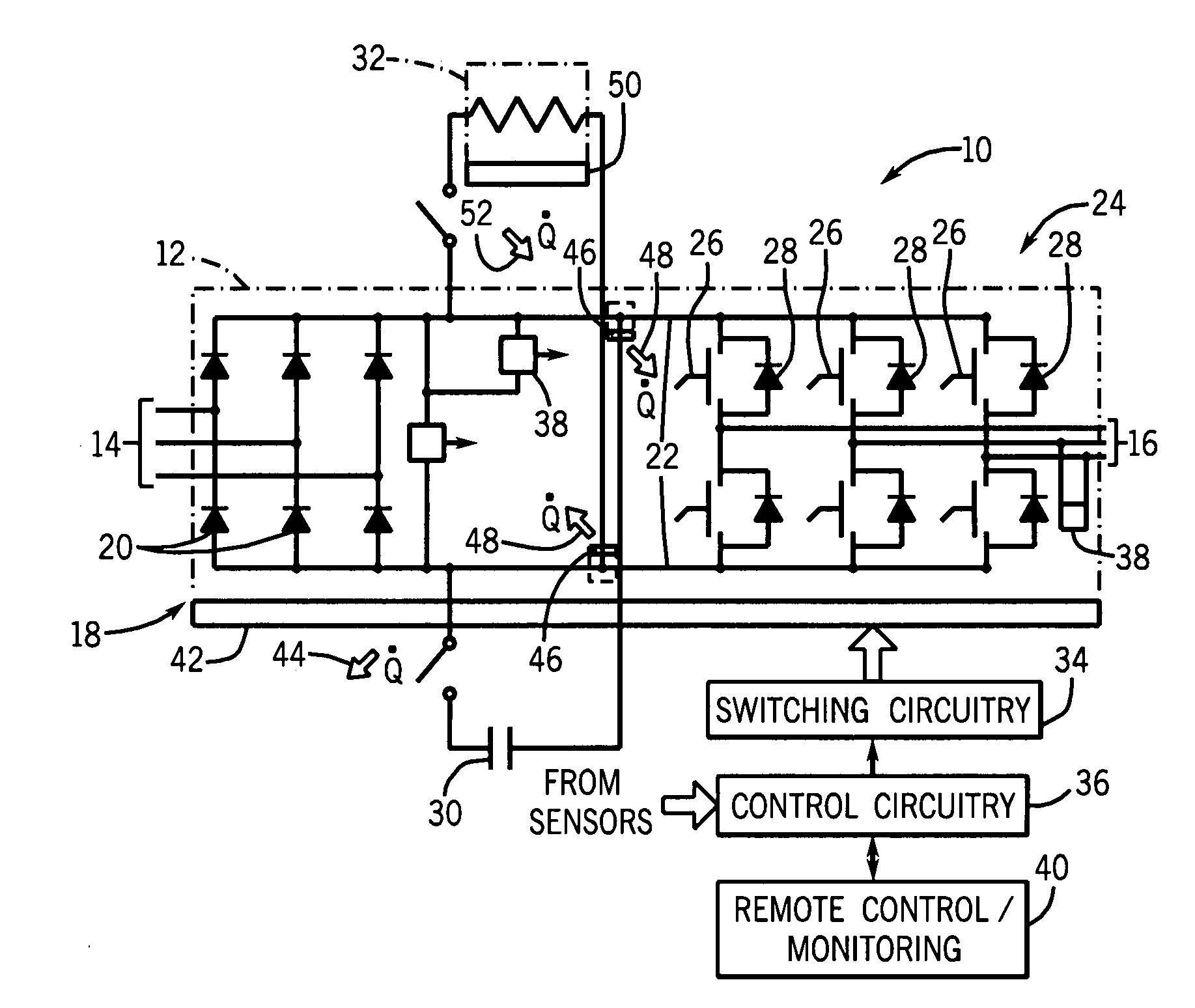
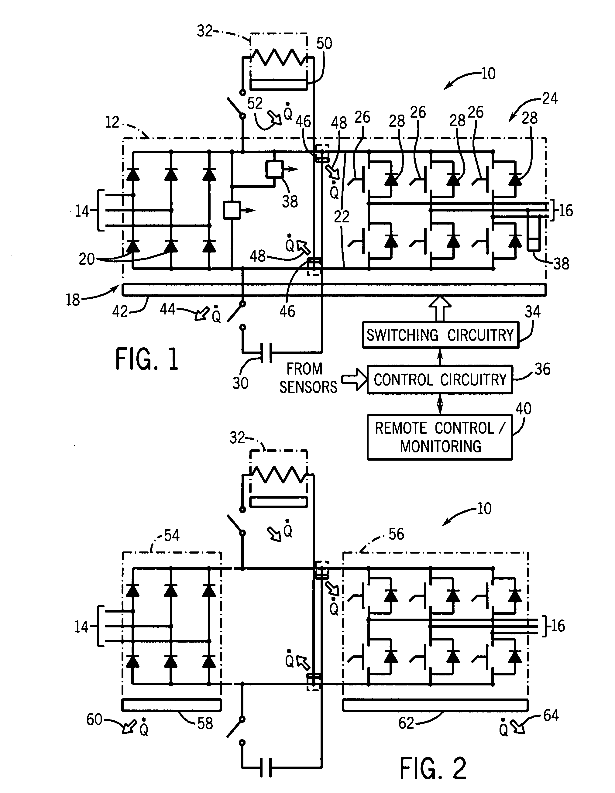
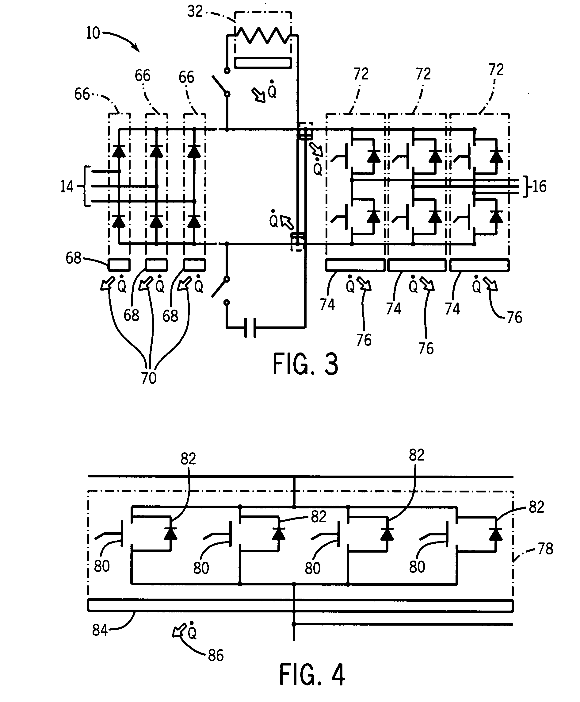
[0026]Turning now to the drawings, and referring first to FIG. 1, an exemplary power electronic circuit 10 is illustrated in which phase change heat spreaders or cooling devices are employed in accordance with aspects of the invention. In the illustrated embodiment, circuit 10 forms a power module 12, such as for a motor drive. The power module is adapted to receive three-phase power from a line side 14 and to convert the fixed frequency input power to control frequency output power delivered at a load side 16. While an inverter circuit will generally be described below as an example of an application of the present invention, it should be borne in mind throughout this discussion that the invention is not limited to this or any particular power electronic circuit. Indeed, the invention may be used in inverter applications, converter applications, AC-to-AC circuitry, AC-to-DC circuitry, DC-to-AC circuitry, and DC-to-DC circuitry. Certain of the inventive aspects may be applied in a w...


PUM


Abstract

A technique is disclosed for cooling connections points in power electronic circuits, such as points at which wire bonding connections are made. A phase change heat spreader is thermally coupled at or near the connection point and a continuous phase change takes place in the heat spreader to extract heat from the connection point during operation. The heat spreader may extend over a area larger than the connection point to enhance cooling and to dissipate heat over a larger area. Small, specifically directed applications are possible in which specific points are cooled together or individually.

Description

BRIEF DESCRIPTION[0001]The present invention relates generally to thermal management and heat dissipation in power electronic circuits as similar environments.[0002]Power electronic circuitry is used in a wide range of industrial and other applications. For example, single and three-phase circuits are used to convert AC power to DC power, and DC power to AC power, AC power directly to AC power with other power characteristics, and so forth. In general, such circuits are made up of power electronic switching devices, diodes, resistors, and so forth that are controlled to carry out the desired power conversion. Packaging for such devices often leads to challenging thermal management, particularly for extraction of heat from overall circuitry and from specific locations during operation.[0003]In a typical power electronic device, heat originates from a range of sources. For example, heat is generated due to conduction and switching losses in the power electronic components themselves. ...

Claims


Application Information

Patent Timeline
Patent Type & Authority Applications(United States)
IPC IPC(8): H05K7/20
CPCH01L23/427H01L24/02H01L2924/1305H01L2924/13034H01L24/48H01L2224/85H05K7/20936H02M7/003H01L2224/73265H01L2224/49175H01L2224/49111H01L24/49H01L24/85H01L25/072H01L2224/48227H01L2924/00H01L2924/00014H01L24/05H01L2224/04042H01L2224/45099H01L2224/45015H01L2924/207
Inventor WEISS, BRUCE W.PHILLIPS, MARK G.
Owner ROCKWELL AUTOMATION TECH
Learn More