
Disk array apparatus

Active Publication Date: 2008-10-23
RAKUTEN GRP INC
View PDF15 Cites 26 Cited by
  • Summary
  • Abstract
  • Description
  • Claims
  • Application Information

AI Technical Summary

Benefits of technology

[0008]The present invention has been made in consideration of the above-described problems, and an object thereof is to provide a technology by which noises caused by a fan can be prevented and reduced while securing the cooling performance of the whole apparatus in the relatively large disk array apparatus in which high density mounting and cooling performance are taken into consideration.
[0010]In this apparatus, the phases of noises generated from fans are inverted by acoustic means (mechanical and controlled means corresponding thereto), and the inverted noises are overlapped (synthesized) on original sounds on a cooling air flow path, thereby reducing the noise. Moreover, the noise reduction is carried out, while maintaining the cooling performance of the apparatus (exhaust and intake efficiency of cooling air). This configuration uses a basic acoustic principle (referred to as noise reduction by synthesizing phase-inverted sounds, first means, and the like), in which the noise element is cancelled (noise cancellation) by overlapping a sound wave (second sound), whose phase is inverted, on an original sound wave (first sound) corresponding to a noise element (specific frequency) of a fan. In this apparatus, by taking note of a specific (inherent) frequency to be a noise element of the sounds generated from the fans provided in the apparatus, a sound (second sound) whose phase is inverted for the wavelength (λ) thereof is produced by predetermined means such as a duct structure, and the noise is reduced by overlapping the second sound on the original sound (first sound). In this manner, noises are reduced in comparison with, at least, those of a conventional configuration.
[0012]The apparatus has the following configurations as the first means. Also, further improved effects are obtained by adopting the combination of the configurations.
[0022]The effects obtained by typical ones of the inventions disclosed in this application will be briefly described below. According to an aspect of the present invention, noises caused by a fan can be prevented and reduced while securing the cooling performance of the whole apparatus in the relatively large disk array apparatus in which high density mounting and cooling performance are taken into consideration. Furthermore, since high powered fans can be installed in the apparatus owing to the effects of fan noise reduction, cooling performance can be improved, and greater customer satisfaction can be achieved by the noise reduction. For example, it becomes possible to use a high powered fan which has not met noise specifications so far, and the operation speed improvement and the capacity increase of the apparatus can be expected.

Problems solved by technology

However, it causes a problem of a higher noise.
However, there is a possibility that the cooling performance is deteriorated because the above measures become the interference against the intake and exhaust of cooling air.

Method used


Image

  • Disk array apparatus
  • Disk array apparatus
  • Disk array apparatus

Examples


first embodiment

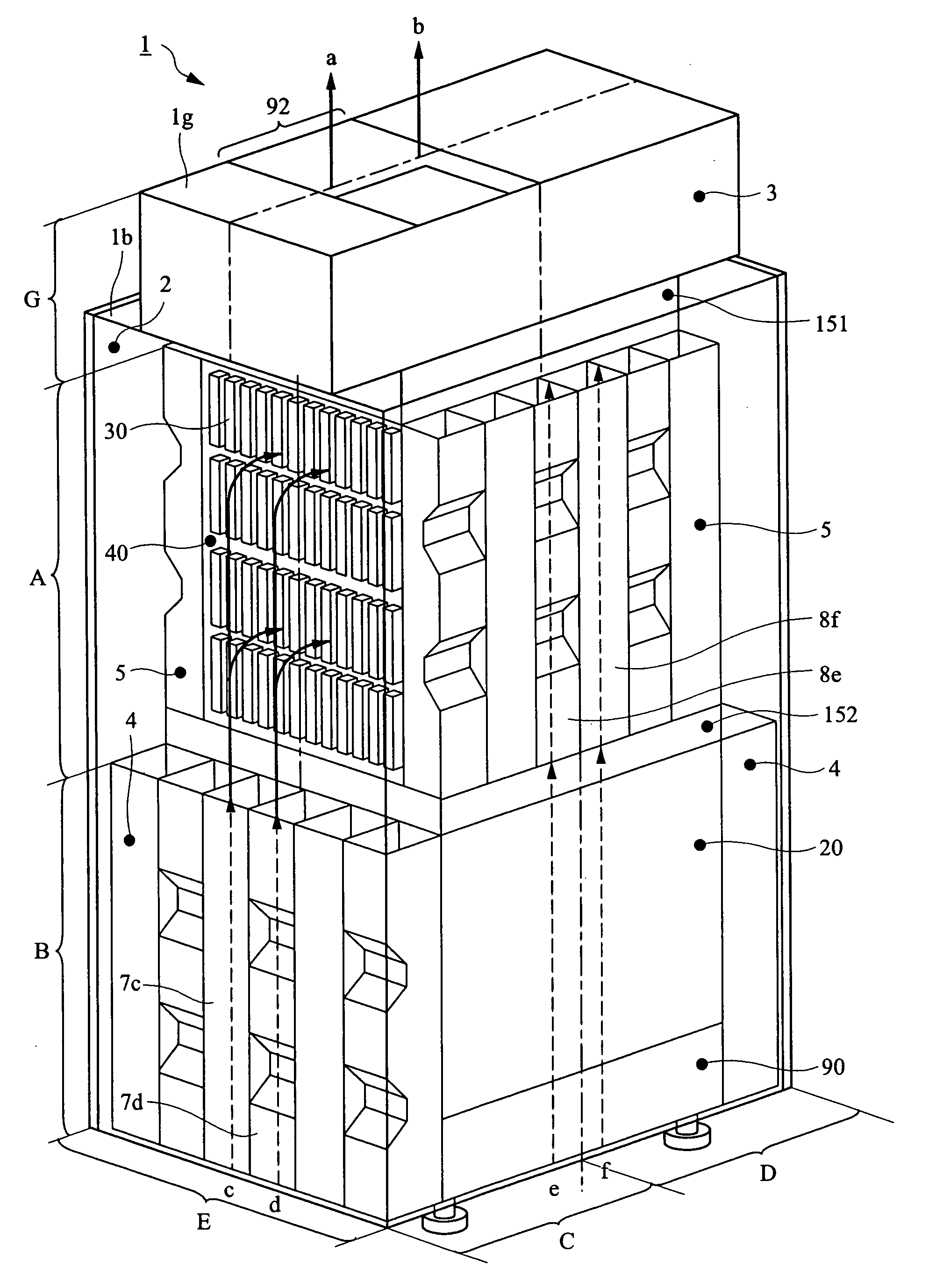
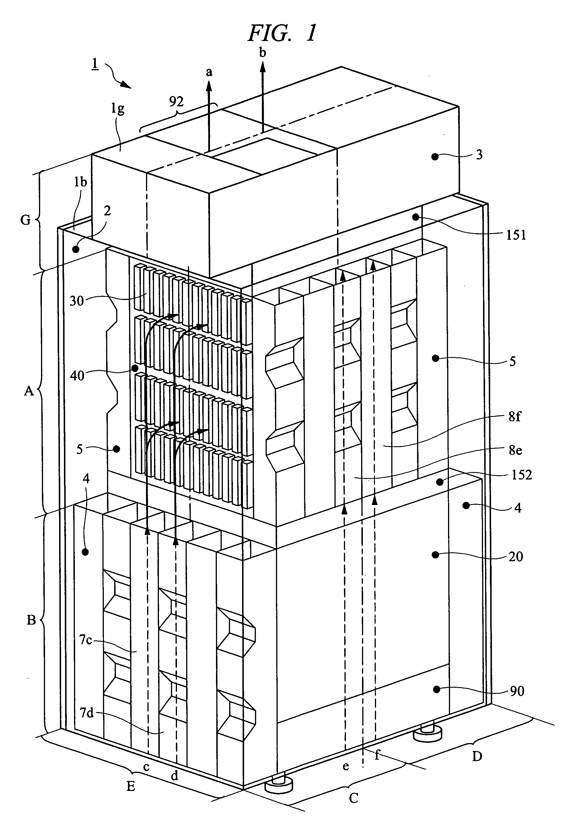
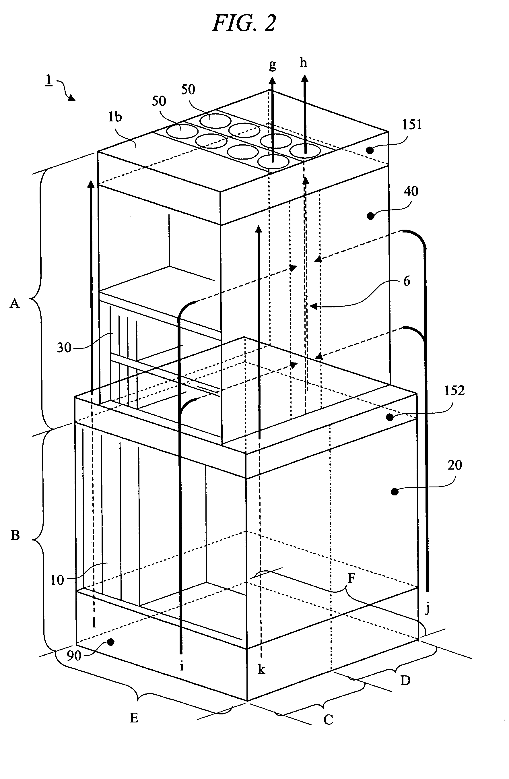
[0045]A disk array apparatus according to a first embodiment of the present invention will be described with reference to FIG. 1 to FIG. 5.

[0046]

[0047]The first embodiment is characterized in that, as a noise reduction configuration for fan units 151 and 152 using the synthesis of phase-inverted sounds (first means), the following noise reduction structures are provided, that is: (1) a noise reduction structure using an exhaust duct 3 in the uppermost part G (corresponding to a first cooling air flow path and the first fan unit 151); (2) a noise reduction structure using a first side duct unit 4 in the lower half part B (corresponding to the first cooling air flow path and the first fan unit 151); and (3) a noise reduction structure using a second side duct unit 5 in the upper half part A (corresponding to a second cooling air flow path and the second fan unit 152). Further, the structure (4) is also provided, in which a noise insulation cover 2 is disposed on the outermost peripher...

second embodiment

[0080]Next, a disk array apparatus 1 according to a second embodiment of the present invention will be described with reference to FIG. 6. The second embodiment has a basic configuration similar to that of the first embodiment, and the feature of the second embodiment lies in the noise reduction structure using an exhaust duct 3 in the uppermost part G, in which a cooling air flow path is divided into a plurality of paths by partition plates 93.

[0081]In FIG. 6, as a second configuration example of the exhaust duct 3, the inside of the exhaust duct 3 is divided into a plurality (four in the this embodiment) of similar spaces and flow paths by a plurality (three in this embodiment) of partition plates 93. The first fan unit 151, the partition plate 91 in the horizontal direction and the exhaust port 92 have the same configurations as those of the first configuration example shown in FIG. 5. The partition plate 93 has a rectangular shape with the same size as that of the side surface o...

third embodiment

[0092]Next, a disk array apparatus 1 according to a third embodiment of the present invention will be described with reference to FIG. 9. The third embodiment has a basic configuration similar to that of the first embodiment, and the feature of the third embodiment lies in that the blades are arranged to form two-stage configuration in a plurality of (at least one) fans 50 in the first fan unit 151 (or the second fan unit 152), and the noise reduction is realized by producing and synthesizing phase-inverted sounds by the two-stage configuration.

[0093]As shown in FIG. 9A and FIG. 9B, a plurality of (N: for example, four) blades (upper-stage blades) 51 are arranged so as to be shifted by equal angles (for example, 90 degrees) to a rotation axis 53 in the upper stage, and a plurality (N: for example, four) blades (lower-stage blades) 52 are arranged so as to be shifted by equal angles (for example, 90 degrees) in the lower stage. Then, the group of the upper-stage blades 51 and the gro...


PUM


Abstract

In a disk array apparatus, by taking note of a first sound of a specific frequency which is a noise element of original sounds generated from a fan, a second sound whose phase is inverted to that of the first sound is generated by a structure of a cooling air flow path passing through the fan, and the second sound is synthesized with the first sound on the cooling air flow path, thereby reducing the noise. For example, an exhaust duct is located on a fan unit in an upper part of the apparatus, two flow paths extending to an exhaust port are formed in an internal structure of the exhaust duct, and the two flow paths are designed so that the difference in the flow path length therebetween becomes equivalent to half wavelength of the specific frequency.

Description

CROSS-REFERENCE TO RELATED APPLICATION[0001]The present application claims priority from Japanese Patent Application No. JP 2007-108075 filed on Apr. 17, 2007, the content of which is hereby incorporated by reference into this application.TECHNICAL FIELD OF THE INVENTION[0002]The present invention relates to a disk array apparatus (also called a storage apparatus and others) having a function to control a storage device such as a hard disk drive (HDD). More particularly, it relates to a cooling structure by means of fans (blower) and a noise reduction and soundproof structure of the apparatus.BACKGROUND OF THE INVENTION[0003]In recent years, disk array apparatus with higher mounting density and higher performance has been developed. Accordingly, higher cooling performance has also been demanded in order to cope with the temperature rise due to the increase in heat generation of component parts and resulting performance deterioration.[0004]For example, in a comparatively large disk a...

Claims


Application Information

Patent Timeline
IPC IPC(8): H05K7/20
CPCG06F1/182G06F1/20G11B17/26G11B33/142H05K7/20736Y10S454/906
Inventor FUKUDA, HIROSHIMATSUSHIMA, HITOSHI
Owner RAKUTEN GRP INC
Learn More