Multilens member, illumination apparatus, and liquid crystal display apparatus

a technology which is applied in the direction of lighting and heating apparatus, instruments, other domestic objects, etc., can solve the problems of increased thickness of illumination apparatus and liquid crystal display apparatus, increased absorption of transmitted light, and deterioration of optical performance, so as to achieve low cost and reduce the effect of optical performance and thinness

Inactive Publication Date: 2008-10-23
HITACHT MAXELL LTD
View PDF8 Cites 12 Cited by
  • Summary
  • Abstract
  • Description
  • Claims
  • Application Information

AI Technical Summary

Benefits of technology

[0012]As described above, in the conventional liquid crystal display apparatus and / or the illumination apparatus called “backlight unit” to be installed on the back surface of the display device such as the liquid crystal panel, a plurality of optical sheets ( for example, two prism sheets) are stacked. When the number of sheets is increased, the scattering and the absorption of the transmitted light are increased, and the optical performance is deteriorated. Further, when the number of sheets is increased, problems arise, for example, such that the thicknesses of the illumination apparatus and the liquid crystal display apparatus are increased, and the cost is raised.
[0013]The present invention has been made in order to solve the problems as described above, an object of which is to provide an optical member as well as an illumination apparatus and a liquid crystal display apparatus provided with the same, wherein it is possible to improve the optical performance of the illumination apparatus and the liquid crystal display apparatus and it is possible to realize the thin sizes (small sizes) and the low cost of the illumination apparatus and the liquid crystal display apparatus.

Problems solved by technology

When the number of sheets is increased, the scattering and the absorption of the transmitted light are increased, and the optical performance is deteriorated.
Further, when the number of sheets is increased, problems arise, for example, such that the thicknesses of the illumination apparatus and the liquid crystal display apparatus are increased, and the cost is raised.

Method used


Image

  • Multilens member, illumination apparatus, and liquid crystal display apparatus
  • Multilens member, illumination apparatus, and liquid crystal display apparatus
  • Multilens member, illumination apparatus, and liquid crystal display apparatus

Examples


first embodiment

[0060]In this first embodiment, an explanation will be made about a liquid crystal display apparatus as well as an illumination apparatus and a multilens member to be used therefor.

Arrangement of Liquid Crystal Display Apparatus and Backlight Unit

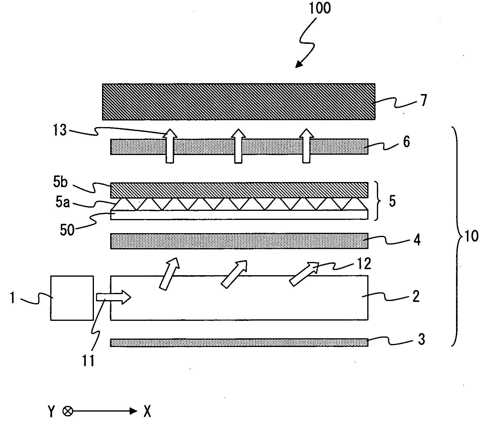
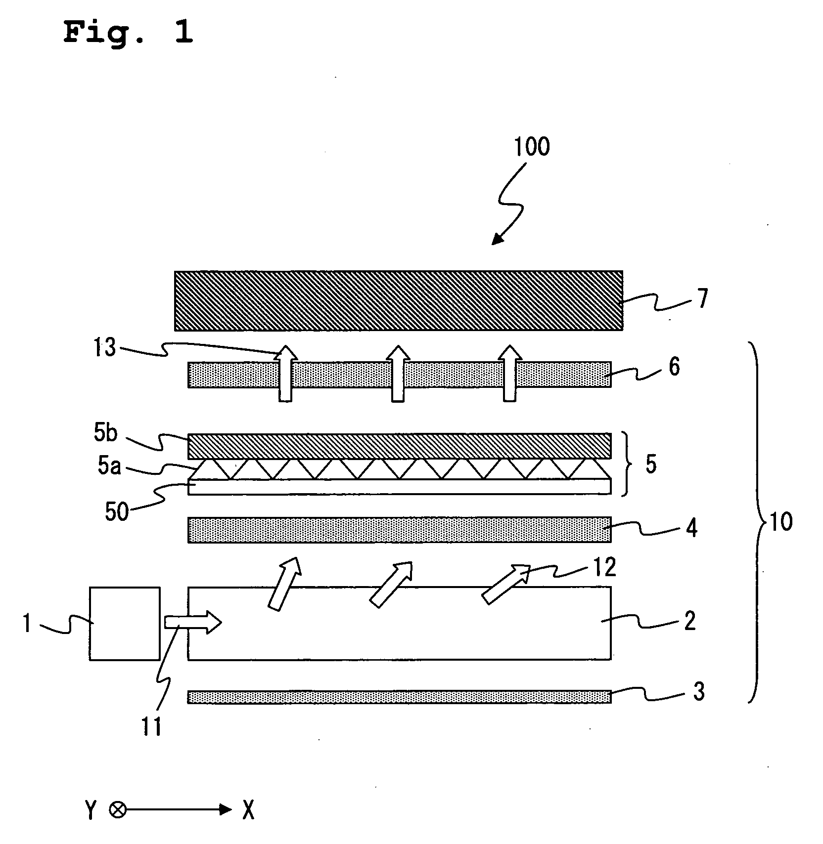
[0061]FIG. 1 shows a schematic arrangement of the liquid crystal display apparatus used in the first embodiment. In FIG. 1, the respective optical members are depicted separately in order to comprehensively understand the arrangement of the liquid crystal display apparatus. However, the respective optical members are stacked in a state of making contact with each other in the actual apparatus. As shown in FIG. 1, the liquid crystal display apparatus 100 of this embodiment comprises a liquid crystal display panel 7 (liquid crystal display device) and a backlight unit 10 (illumination apparatus).

[0062]A liquid crystal display panel used in the conventional liquid crystal display apparatus was used for the liquid crystal display panel 7. Speci...

second embodiment

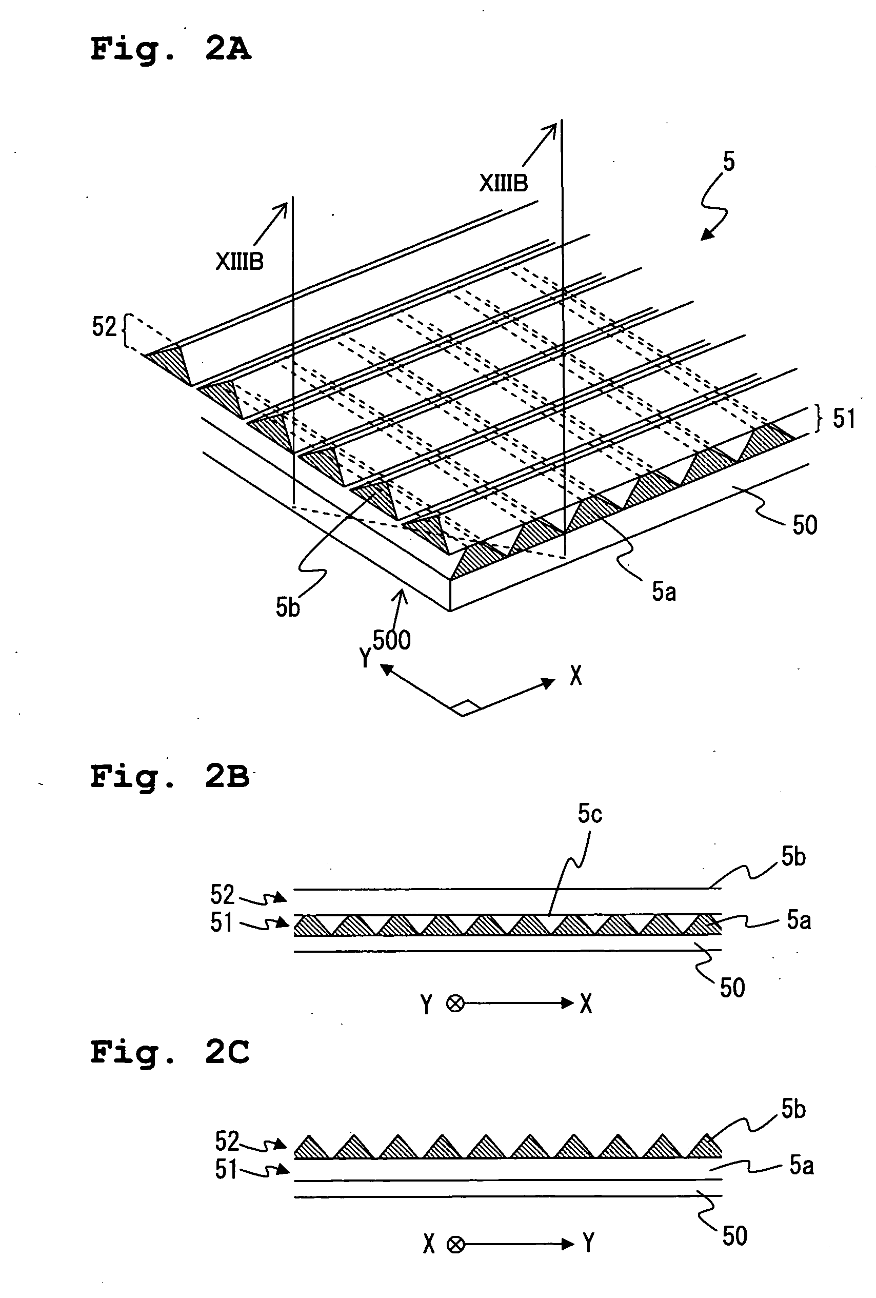
[0096]In this second embodiment, a multilens sheet, which had the same or equivalent structure (structure shown in FIG. 2) as that of the first embodiment, was manufactured. However, in this embodiment, the multilens sheet was manufactured by means of a method which was different from the method in the first embodiment. The base member, the first prism-shaped structures, and the second prism-shaped structures, which constituted the multilens sheet manufactured in this embodiment, had the same sizes as those of the first embodiment. The method for manufacturing the multilens sheet of this embodiment will be explained below with reference to FIGS. 2, 9, and 10. FIG. 10 shows a flow chart illustrating the procedure of the method for producing the multilens sheet of this embodiment.

[0097]At first, the first optical adjusting layer 51 (the plurality of first prism-shaped structures 5a) was formed on the base member 50 in the same manner as in the first embodiment (Steps S21 and S22 shown...

third embodiment

[0107]In this third embodiment, a multilens sheet, which had the same or equivalent structure (structure shown in FIG. 2) as that of the first embodiment, was manufactured. However, in this embodiment, the multilens sheet was manufactured by means of a method which was different from the methods adopted in the first and second embodiments. In this embodiment, the sizes and the materials for forming the base member, the first prism-shaped structures, and the second prism-shaped structures for constructing the multilens sheet were changed from those of the first and second embodiments.

[0108]A polyethylene terephthalate (PET) sheet having a thickness of 50 μm was used as the base member 50.

[0109]The first prism-shaped structures 5a were formed of an ultraviolet-curable resin. The first prism-shaped structure 5a had a refractive index of 1.59. The cross-sectional shape of the first prism-shaped structure 5a was such a shape that an apex portion of an isosceles triangle having an apex an...


PUM

PropertyMeasurementUnit
angleaaaaaaaaaa
thicknessaaaaaaaaaa
thicknessaaaaaaaaaa

Abstract

A multilens member is provided, the multilens member including a base member which has light transmissivity; a plurality of first lenses which are formed on the base member; and a plurality of second lenses which are formed on the plurality of first lenses and which are joined to the plurality of first lenses on first surfaces opposed to the base member; wherein the first surfaces of the second lenses have junction which are joined to the first lenses and overhang which overhangs outwardly from the junction portions. That is, the multilens member having the overhang shape is provided. Accordingly, it is possible to provide the optical member which improves the optical performance of an illumination apparatus and which realizes the thin size and the low cost of the illumination apparatus and a liquid crystal display apparatus.

Description

CROSS REFERENCE TO RELATED APPLICATION[0001]The present application claims priority from Japanese Patent Application Nos. 2007-110818 and 2008-89480, filed on Apr. 19, 2007, and Mar. 31, 2008, respectively, the disclosure of which is incorporated herein by reference in its entirety.BACKGROUND OF THE INVENTION[0002]1 Field of the Invention[0003]The present invention relates to a multilens member which controls the directivity of the incident light, the multilens member having an overhang shape. The present invention also relates to an illumination apparatus and a liquid crystal display apparatus based on the use of the same.[0004]2. Description of the Related Art[0005]Conventionally, various types of illumination apparatuses, such as backlight units for liquid crystal displays, are provided with any mechanism for adjusting the brightness and the broadening of the light beam emitted from the light source. In most of the illumination apparatuses, an optical member such as an optical sh...

Claims


Application Information

Patent Timeline
Patent Type & Authority Applications(United States)
IPC IPC(8): G02F1/1335F21V7/04
CPCG02B6/0053B29D11/0073B29D11/00788
Inventor SHIMAZAKI, KATSUSUKEOGAWA, YOUICHISATO, MASATAKAKOYAMA, EIJI
Owner HITACHT MAXELL LTD
Why Eureka
Try Eureka