Cutting insert

a cutting insert and insert technology, applied in the field of cutting inserts, can solve the problems of chip blockage and inability to be smoothly disposed, and achieve the effects of lubrication and cooling, preventing the increase of cutting resistance and the blockage of chips, and smooth disposed

Inactive Publication Date: 2008-10-02
MITSUBISHI MATERIALS CORP
View PDF7 Cites 23 Cited by
  • Summary
  • Abstract
  • Description
  • Claims
  • Application Information

AI Technical Summary

Benefits of technology

[0009]The present invention is achieved in view of the above-mentioned circumstances and has an object to provide a cutting insert which is used for grooving and cutting-off of a work material as mentioned above, in which chips can be smoothly disposed without increasing a cutting resistance even when a cutting insert is fed in a traverse direction in order to broaden a groove width in the grooving operation.

Problems solved by technology

Therefore, the reentrant portion of the outer wall face is clogged with the chips pushed therein; as a result, the chips cannot be smoothly disposed and a cutting resistance would be increased.

Method used


Image

  • Cutting insert
  • Cutting insert
  • Cutting insert

Examples


first embodiment

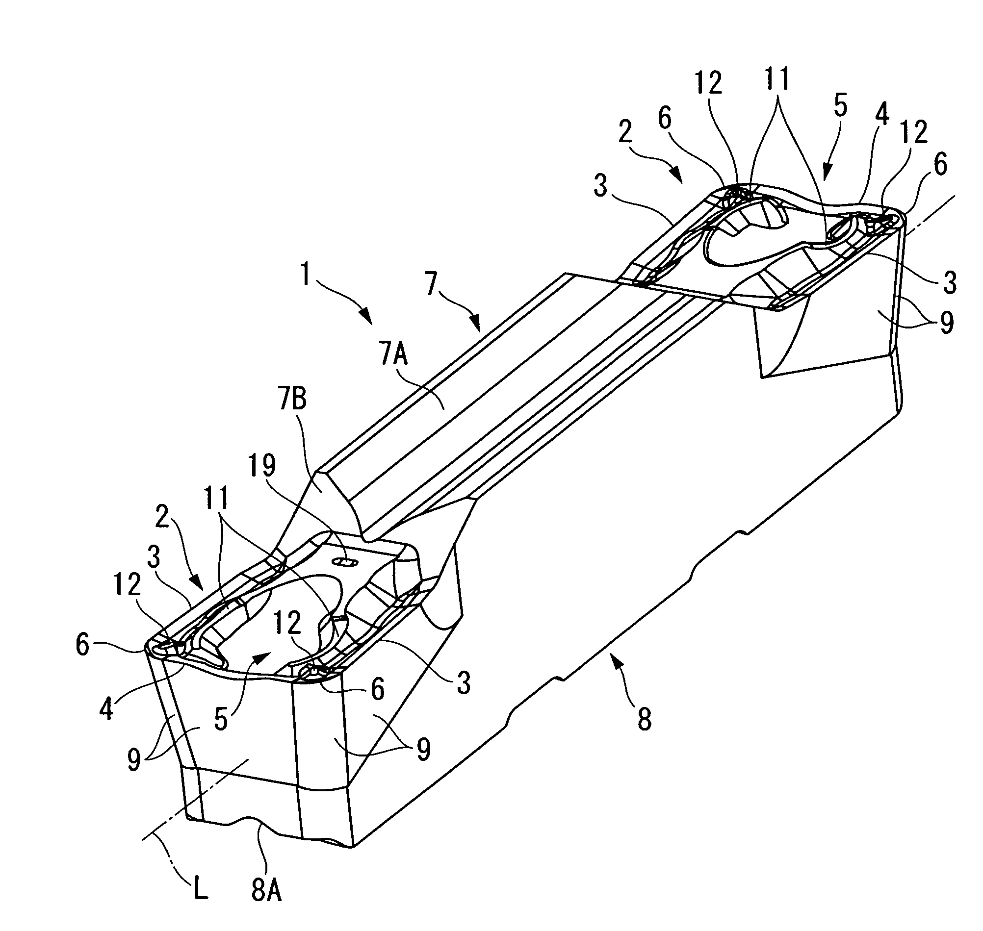
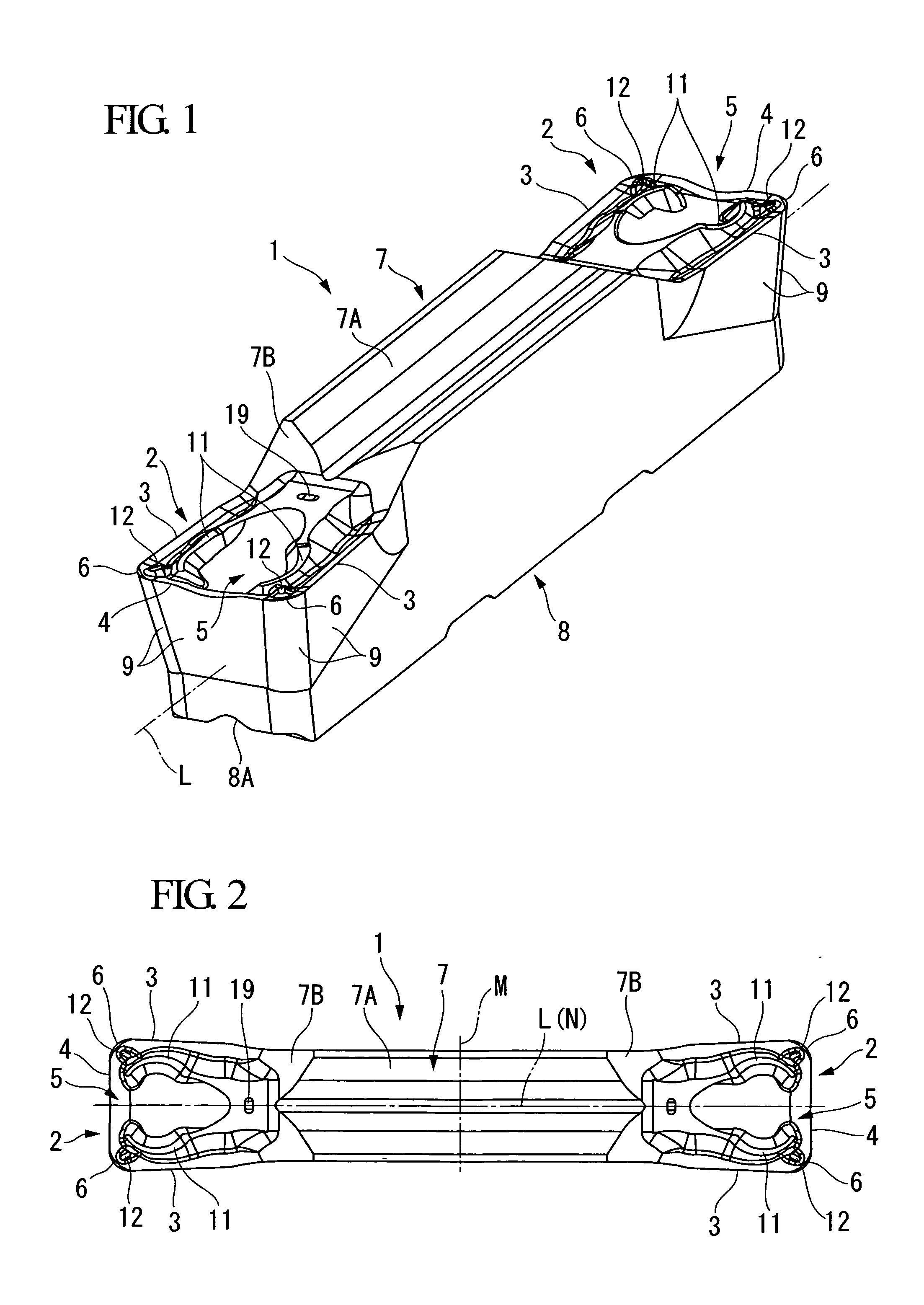
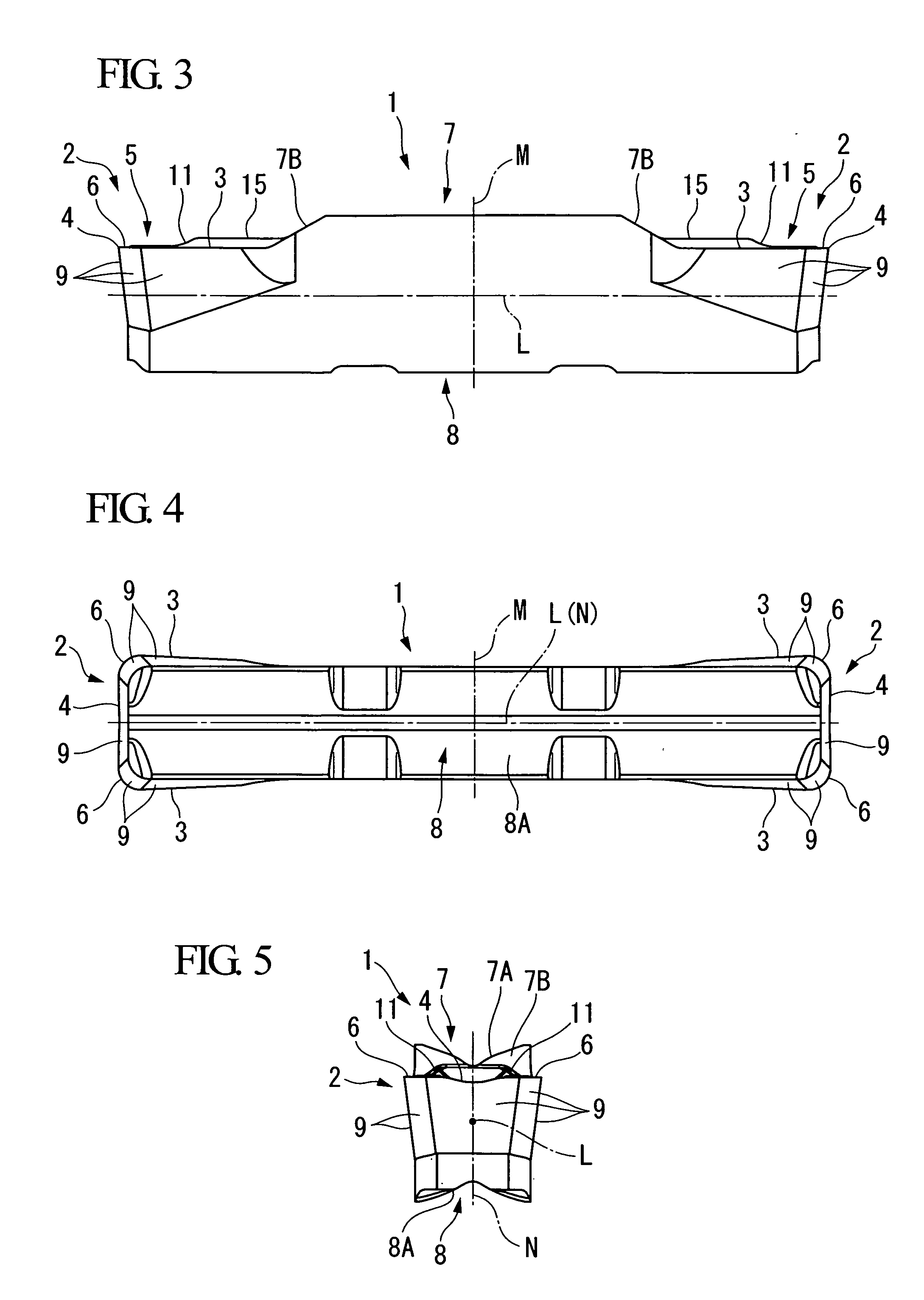
[0073]FIGS. 1 to 7 show a cutting insert according to the present invention. An insert body 1 of the present embodiment is formed from a hard material such as cemented carbide or the like, and has substantially a square shaft shape (a square pillar shape) extending along an axis L. The insert body 1 is formed so as to substantially be symmetrical about a plane M perpendicular to the axis L at a center in a longitudinal direction (i.e., the axis L direction; in other words, a left and right direction of FIGS. 2 to 4) of the insert body 1. Further, the insert body 1 is formed so as to be symmetrical about a plane N at a center in a width direction (i.e., an up and down direction in FIGS. 2 and 4) of the insert body 1. The plane N is perpendicular to the plane M, includes the axis L, and extends in a thickness direction (i.e., an up and down direction in FIGS. 3 and 5) of the insert body.

[0074]A cutting edge portion 2 is formed at each of end portions of the insert body 1 in the longit...

second embodiment

[0100]In the present embodiment, the center of the circular arc of the intersection ridge of the outer wall face 14 and the protruded end face 15 is located between the axis L and the circular arc as seen in the plan view. However, the center may be located on the axis L as seen in the plan view; that is, the intersection ridges of the outer wall faces 14 and the protruded end faces 15 of the pair of protruded streaks 11 can be formed on one circle. Further, for example, as an insert body 101 of the present invention shown in FIG. 9, the center of the circular arc of the outer wall face 114 of the protruded streak 111 may be located at the far side of the axis L as seen in the plan view so that the radius R12 is large.

[0101]In the second embodiment, it can be prevented that the portion of the outer wall face 114 to which the chips collide is too small so that the chips are not sufficiently broken by the bend, when most of portion of the side cutting edge 3 is used in order to broade...


PUM

PropertyMeasurementUnit
angleaaaaaaaaaa
angleaaaaaaaaaa
angleaaaaaaaaaa

Abstract

A cutting insert has an insert body having a shaft-shape, wherein a cutting edge portion having a square rake face is formed on an end portion of the insert body, and wherein the rake face includes: a pair of side cutting edges extending in a longitudinal direction of the insert body; a front cutting edge extending in a transverse direction perpendicular to the longitudinal direction between each front ends of the side cutting edges; and a pair of protruded streaks extending toward a corner portion at which each of the side cutting edges intersects the front cutting edge, each of the protruded streaks including an outer wall face having a protruded curved face which faces the adjacent side cutting edge and protrudes toward the side cutting edge as seen in a direction facing the rake face and perpendicular to the longitudinal direction.

Description

BACKGROUND OF THE INVENTION[0001]1. Field of the Invention[0002]The present invention relates to a cutting insert which is used in turning operations of work materials for grooving, cutting-off, or the like.[0003]Priority is claimed on Japanese Patent Application No. 2007-091952, filed Mar. 30, 2007, Japanese Patent Application No. 2007-094884, filed Mar. 30, 2007, and Japanese Patent Application No. 2008-012975, filed Jan. 23, 2008, the contents of which are incorporated herein by reference.[0004]2. Description of the Related Art[0005]A cutting insert for grooving, cutting-off or the like used in turning operations is proposed, for example, in Japanese Unexamined Patent Application, First Publication No. H09-174308 (hereinafter, JP H09-174308), so as to have a pair of ridges extending substantially in the longitudinal direction on a top surface of a cutting head, a chip breaker pit which is provided between the ridges, a break line extending between a front pit and a rear pit of th...

Claims


Application Information

Patent Timeline
Patent Type & Authority Applications(United States)
IPC IPC(8): B23B27/16
CPCB23B27/045Y10T407/23B23B2200/081
Inventor NAGAYA, HIDEHIKOASO, NORIOIMAI, YASUHARU
Owner MITSUBISHI MATERIALS CORP
Why Eureka
Try Eureka