
Capacitors adapted for acoustic resonance cancellation

a technology of capacitors and acoustic resonance, applied in the direction of variable capacitors, capacitors with electrode area variation, fixed capacitors, etc., can solve the problems of low power handling capability, low q, high nonlinearity, etc., to reduce acoustic losses, improve q, and reduce losses

Active Publication Date: 2008-09-25
NXP USA INC
View PDF59 Cites 34 Cited by
  • Summary
  • Abstract
  • Description
  • Claims
  • Application Information

AI Technical Summary

Benefits of technology

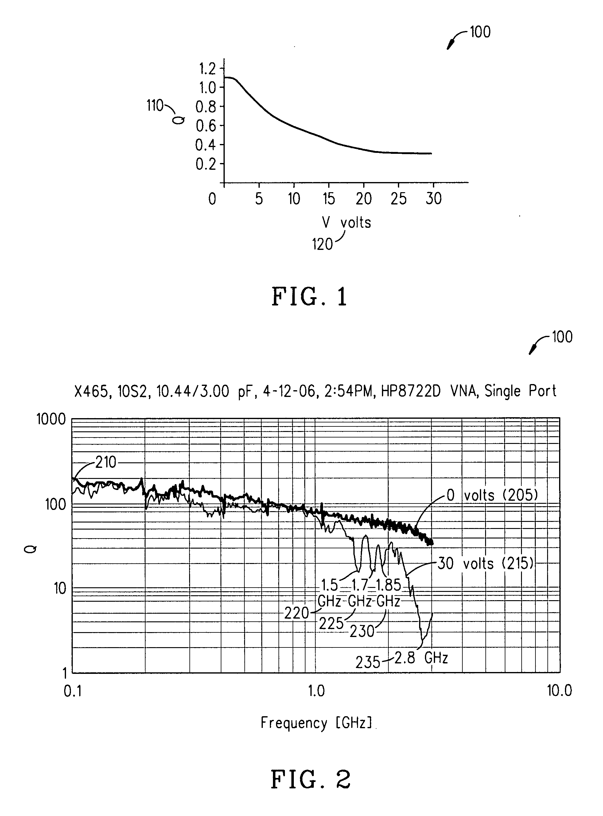
[0011]An embodiment of the invention further provides a method, comprising reducing the losses due to electro-mechanical coupling and improving Q in a multilayered capacitor by placing a first capacitor layer adjacent at least one additional capacitor layer and sharing a common electrode in between the two such that the acoustic vibration of the first layer is coupled to an anti-phase acoustic vibration of the at least one additional layer.
[0012]Still another embodiment of the present invention provides a multilayered tunable capacitor, comprising a first voltage tunable dielectric layer, at least one additional voltage tunable dielectric layer adjacent to the first voltage tunable dielectric layer and sharing a common electrode in between the two, and wherein any acoustic vibration of the first voltage tunable dielectric layer caused by the application of combined AC and DC voltages is coupled to a corresponding acoustic vibration caused by the application of the combined AC and DC voltages to the at least one additional voltage tunable dielectric layer, thereby reducing acoustic losses and improving Q.
[0013]Yet another embodiment of the present invention provides, a device, comprising a single layered varactor consisting of at least two capacitors connected in series to an RF signal and adapted to reduce acoustic losses and improve Q. The adjacent electrodes of the at least two capacitors may be positioned to vibrate in opposite phases thereby reducing acoustic losses and improving Q. Further, a DC bias may be applied across the at least two capacitors from a top to a bottom electrode.
[0014]Yet another embodiment of the present invention provides a method, comprising reducing the acoustic losses and improving Q in a single layered varactor by connecting at least two capacitors in series to an RF signal so that adjacent electrodes of the at least two capacitors vibrate in opposite phase. In the present method, the DC bias may be applied across the at least two capacitors from a top to a bottom electrode and the at least two capacitors may produce acoustic waves of the opposite phase which cancel and wherein by placing a first capacitor adjacent to at least one additional capacitor, the acoustic wave of the first capacitor may be coupled to and cancel an opposite phase acoustic wave of the at least one additional capacitor.
[0015]Still another embodiment of the present invention provides a device, comprising at least two capacitors connected in series to an RF signal and adapted to reduce acoustic losses and improve Q, wherein adjacent electrodes of the at least two capacitors may be positioned to have maximal interimposing of acoustic vibrations with opposite phases thereby reducing acoustic losses and improving Q. The DC bias may be applied across the at least two capacitors in opposite directions.

Problems solved by technology

The most commonly used varactor is a semiconductor diode varactor, which has the advantages of high tunability and low tuning voltage, but suffers low Q, low power handling capability, high nonlinearity and limited capacitance range.
Much design effort must be used to choose the layer materials and their thicknesses to minimize or eliminate the acoustic losses at the desired frequencies of operation; however, it may be impossible to completely eliminate the losses within the desired frequency band(s) because of conflicting performance requirements for the device.

Method used


Image

  • Capacitors adapted for acoustic resonance cancellation
  • Capacitors adapted for acoustic resonance cancellation
  • Capacitors adapted for acoustic resonance cancellation

Examples


Embodiment Construction

[0025]In the following detailed description, numerous specific details are set forth in order to provide a thorough understanding of the invention. However, it will be understood by those skilled in the art that the present invention may be practiced without these specific details. In other instances, well-known methods, procedures, components and circuits have not been described in detail so as not to obscure the present invention.

[0026]An embodiment of the present invention provides a two layer capacitor in which the two layers produce acoustic vibrations of the opposite phase which cancel—although it is understood that the present invention is not limited to two layers. By placing one capacitor in intimate physical contact with the other and sharing a common electrode in between the two, the acoustic vibration of one capacitor is coupled to acoustic vibrations of the other. It is understood that the layers being adjacent in any arrangement is intended to be within the scope of th...


PUM


Abstract

An embodiment of the present invention provides a device, comprising a multilayered tunable dielectric capacitor, wherein said multilayers of tunable dielectric are adapted to be DC biased to reduce the dielectric constant; and wherein the DC bias is arranged so that the number of layers of tunable dielectric biased positively is equal to the number of layers of tunable dielectric biased negatively.

Description

BACKGROUND OF THE INVENTION[0001]Varactors are voltage tunable capacitors in which the capacitance is dependent on a voltage applied thereto. Although not limited in this respect, this property has applications in electrically tuning radio frequency (RF) circuits, such as filters, phase shifters, and so on. The most commonly used varactor is a semiconductor diode varactor, which has the advantages of high tunability and low tuning voltage, but suffers low Q, low power handling capability, high nonlinearity and limited capacitance range. A new type of varactor is a ferroelectric varactor in which the capacitance is tuned by varying the dielectric constant of a ferroelectric material by changing the bias voltage. Ferroelectric varactors have high Q, high power handling capacity, good linearity and high capacitance range.[0002]The use of barium titanate, strontium titanate, or barium strontium titanate (BST) of any composition including any doped BST formulation to make tunable capacit...

Claims


Application Information

Patent Timeline
Patent Type & Authority Applications(United States)
IPC IPC(8): H01G7/00
CPCH01G2/00H01G7/06
Inventor OAKES, JAMESMARTIN, JAMESKOZYREV, ANDREYPRUDAN, A.
Owner NXP USA INC
Learn More