Injection Valve

a technology of injection valve and actuator, which is applied in the direction of fuel injection apparatus, machine/engine, feed system, etc., can solve the problems of tolerance-dictated variation in the ratio of voltage to actuator, time-dependent drift can be observed,

Inactive Publication Date: 2008-09-18
ROBERT BOSCH GMBH
View PDF3 Cites 4 Cited by
  • Summary
  • Abstract
  • Description
  • Claims
  • Application Information

AI Technical Summary

Problems solved by technology

This is because on the one hand, a time-dependent drift can be observed between the ratio of voltage to actuator stroke, while on the other hand, a tolerance-dictated variation in the ratio of voltage to actuator is unavoidable.

Method used


Image

  • Injection Valve
  • Injection Valve
  • Injection Valve

Examples


Embodiment Construction

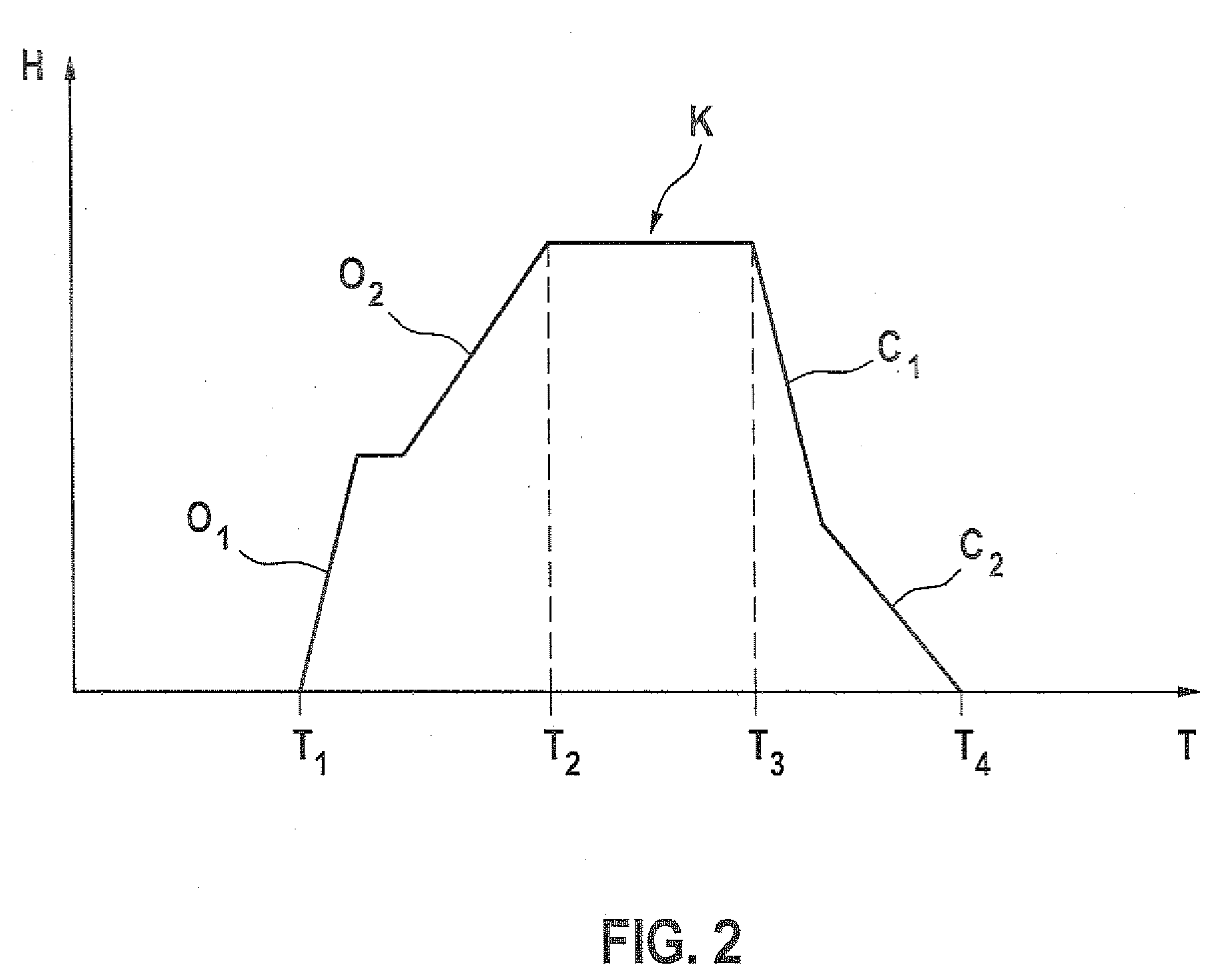
[0013]As shown in FIG. 1, an injection nozzle 1 of the invention includes a nozzle body 2, which has at least one injection port 3. The injection nozzle 1 is intended for an internal combustion engine, which may in particular be disposed in a motor vehicle, and serves to inject fuel into an injection chamber 4, into which the injection nozzle 1 in the installed state protrudes, at least in the region of the at least one injection port 3.

[0014]The injection nozzle 1 includes a nozzle needle 5, which may be a component of a needle combination 6, and with the aid of which an injection of fuel through the at least one injection port 3 can be controlled. To that end, the nozzle needle 5 with its needle tip 7 cooperates with a needle seat 8. If the nozzle needle 5 is seated in its needle seat 8, the at least one injection port 3 is blocked; that is, the at least one injection port 3 is disconnected from a feed path 9 by way of which fuel at injection pressure is furnished and supplied to ...


PUM


Abstract

The present invention relates to an injection nozzle for an internal combustion engine in a motor vehicle. A nozzle body has at least one spray hole, a nozzle needle mounted in the nozzle body with adjustable stroke for controlling an injection of fuel through the at least one spray hole. A booster piston is drive-coupled to an actuator and has a booster face which delimits a booster chamber. According to the invention, the nozzle needle has a control face which delimits a control chamber. In order to dampen the movement of the nozzle needle into its needle seat as the nozzle needle closes, a damping piston is arranged in the nozzle body with an adjustable stroke. The damping piston separates the control chamber from the booster chamber. A damping path is provided in the damping piston to hydraulically connect the control chamber to the booster chamber in a throttled manner.

Description

PRIOR ART [0001]The present invention relates to an injection nozzle for an internal combustion engine, in particular in a motor vehicle, having the characteristics of the preamble to claim 1.[0002]One such injection nozzle is known for instance from German Patent Disclosure DE 10 2005 007 542, filed on Feb. 18, 2005, and includes a nozzle body which has at least one injection port and in which a nozzle needle is supported with an adjustable stroke, with which needle the injection of fuel through the at least one injection port can be controlled. A booster piston is also provided, which is drive-coupled with an actuator and has a booster face that defines a booster chamber. The nozzle needle, or a needle combination that includes the nozzle needle, moreover has a control face that defines a control chamber. In the known injection nozzle, a deflection piston is supported with an adjustable stroke in the booster piston and has a deflection face coupled hydraulically with the booster f...

Claims


Application Information

Patent Timeline
Patent Type & Authority Applications(United States)
IPC IPC(8): F02M61/16
CPCF02M47/027F02M2200/304F02M61/205F02M51/0603
Inventor KURZ, MICHAEL
Owner ROBERT BOSCH GMBH
Why Eureka
Try Eureka