
Flexible current transformer assembly

a current transformer and flexible technology, applied in the direction of transformer/inductance details, instruments, inductances, etc., can solve the problems of inflexibility, added complexity and expense, difficult installation, etc., and achieve the effect of easy calibration, high precision, and easy installation

Active Publication Date: 2008-09-04
GRIDPOINT
View PDF24 Cites 52 Cited by
  • Summary
  • Abstract
  • Description
  • Claims
  • Application Information

AI Technical Summary

Benefits of technology

The present invention provides a cost-effective alternative to metal core CTs for use in electricity metering applications and new applications. The flexible CT sub-system is interfaced directly with an energy monitoring and control system and includes multiple-phase conductors for continuous monitoring of energy output and effective power management, including fault detection. The CT system includes a single electronic assembly for high precision and easy calibration, with built-in precision potentiometers and range selection switches. The CT system also includes a flexible assembly for easy installation in limited space. The CT system includes a current transformer assembly with three closeable loops and an integrator unit for monitoring current in a multiphase circuit. The technical effects of the invention include improved accuracy, reliability, and flexibility for long-term monitoring and management of power distribution.

Problems solved by technology

Metal core CTs are problematic in that they are not flexible and may be difficult to install in applications in which physical space is limited or the primary conductor is relatively large in size or irregular in shape.
This can be a problem of significant concern when retrofitting electricity meters into existing buildings.
The use of an electronic integrator results in added complexity and expense, which are factors contributing to the historically limited use of this device.
These products are generally designed for temporary test applications and are not readily useful or cost-effective for permanent electricity monitoring applications.
There are also passive integrators constructed of capacitors, resistors and / or inductors, but these integrators do not contain an operational amplifier.
Passive integrators tend to be less stable in their output.
However, even active integrators have some drawbacks.
For example, a periodic reset of the operational amplifier may be used so that the output does not ramp, which would be undesirable if the device is used for current monitoring.
Accordingly, until microprocessor-based circuitry became widely available, the Rogowski coil had a drawback in that coil output voltage and power were not large enough to be used with typical monitoring equipment.
Thus, it was difficult to substitute one Rogowski coil for another in the case of a field repair / upgrade.
Recalibration was especially a problem if there was a large difference in the amount of current passing through respective conductors.
Thus, in large current environments CTs often use large, bulky conventional coils that are difficult to position around conductors, particularly at sites where extra space at the conductors is limited.

Method used


Image

  • Flexible current transformer assembly
  • Flexible current transformer assembly
  • Flexible current transformer assembly

Examples


Embodiment Construction

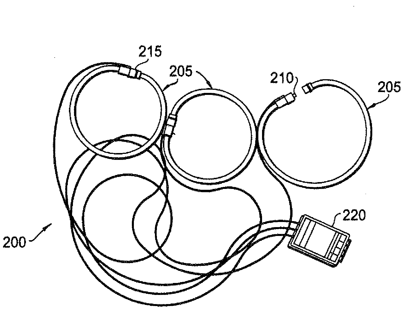
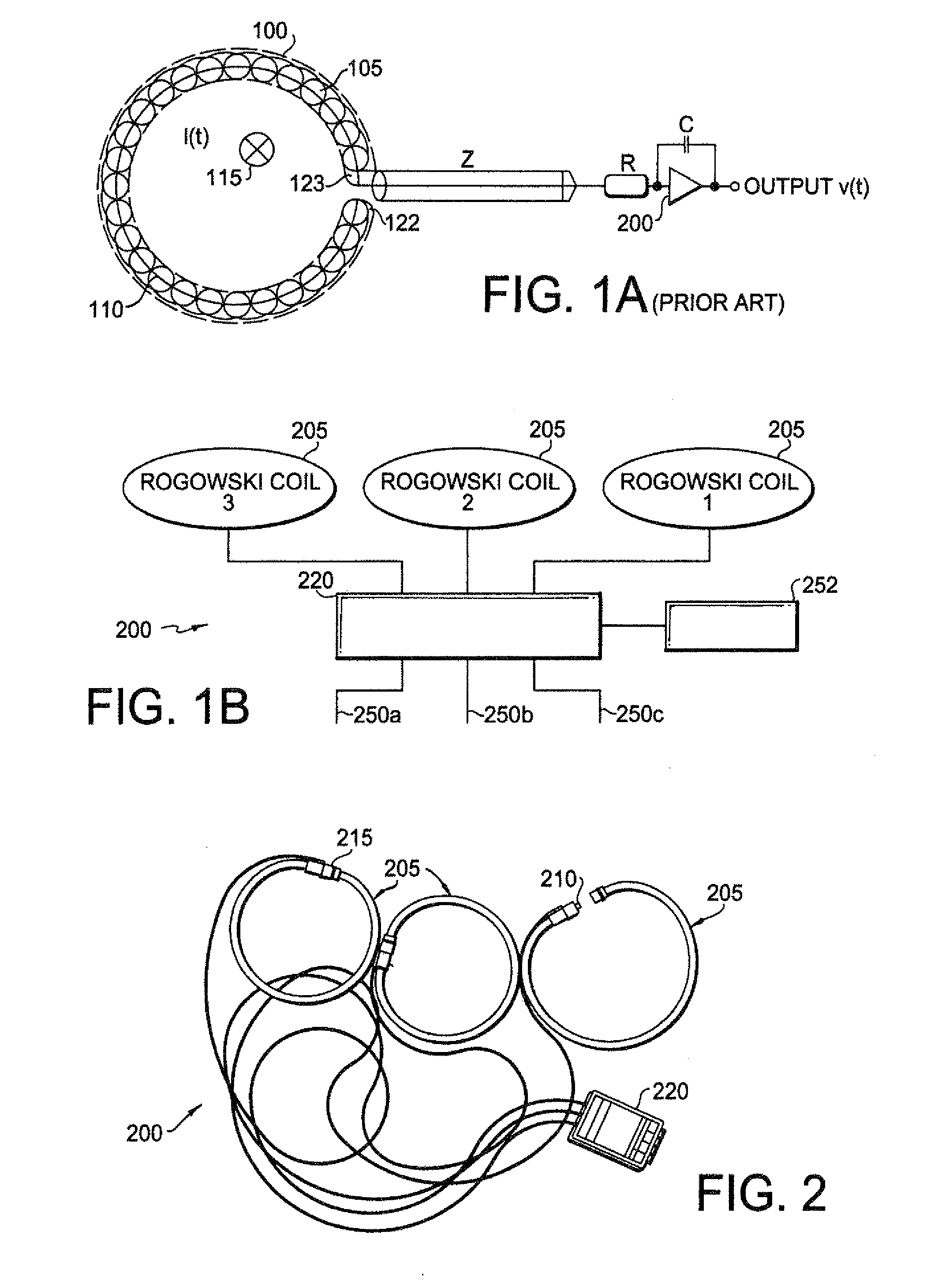
[0037]FIGS. 1B and 2 show a first aspect of a Flexible CT Assembly 200 according to the present invention. There are three Rogowski coils 205 because this particular CT assembly is suitable for use with three phase power, including but in no way limited to, for example, applications such as three phase 208V, three phase 475V, and / or significantly higher values; the amperage through the conductors be monitored can typically be in the 500-2000 amp range, but is also operable at levels much higher or much lower levels, and a person of ordinary skill in the art appreciates that the capabilities of the Flexible CT Assembly can be adapted according to need.

[0038]Referring to FIG. 2, the photo of the Rogowski coils 205 are referred to as “rope coils”, and can typically have an open or free end 210 that can be connected by socket or coil connector mechanism 215. Typically the free end 210 of the coil 205 can snap into the socket or connector. There are coil connector mechanisms 215 that may...


PUM

PropertyMeasurementUnit
electrically conductiveaaaaaaaaaa
voltageaaaaaaaaaa
output voltageaaaaaaaaaa

Abstract

A current transformer assembly includes at least one Rogowski coil having a first closeable loop with an electrically conductive coil member and a first pair of terminals. An integrator unit has respectively a cable connected across the first pair of terminals of a respective Rogowski coil. Each respective Rogowski coil provides an output voltage received by the integrator assembly caused by when a respective electrical conductor on a phase of a multiphase circuit is arranged within an opening of the closeable first loop of the respective Rogowski coil, and provides an output signal proportional to a current in a conductor arranged in an opening of a Rogowski coil. At least one of the Rogowski coils includes an inline calibration unit for fast calibration and recalibration when retrofitting a monitor module that monitors a value of the current in one or more conductors.

Description

CROSS-REFERENCE TO RELATED APPLICATION[0001]This claims priority from U.S. provisional patent application No. 60 / 885,798, filed Jan. 19, 2007, incorporated herein by reference.BACKGROUND OF THE INVENTION[0002]1. Field of the Invention[0003]The present invention relates to a system and a method to integrate Rogowski coils with integrator electronics to create an optimal current transformer (CT) sub-system for use in permanent electricity monitoring. More particularly, the present invention is related to current transformer assemblies. Typically, a current transformer assembly includes at least one Rogowski coil having a first closeable loop with an electrically conductive coil member and a first pair of terminals. An integrator unit has respectively a cable connected across the first pair of terminals of a respective Rogowski coil.[0004]2. Discussion of the Related Art[0005]Devices that measure electricity usage typically employ CTs. CTs are generally installed so that the electrical...

Claims


Application Information

Patent Timeline
Patent Type & Authority Applications(United States)
IPC IPC(8): G01R15/18H01F27/28
CPCG01R15/181H01F38/30H01F27/2895G01R22/06H01F38/28
Inventor HOWELL, DONALD W.TAYLOR, SAMUEL A.DYESS, DANNY K.BLEVINS, FRANK O.VINSON, MARK W.
Owner GRIDPOINT
Learn More