
Cathodic protection monitor

Active Publication Date: 2008-08-28
OLEUMTECH CORP
View PDF6 Cites 39 Cited by
  • Summary
  • Abstract
  • Description
  • Claims
  • Application Information

AI Technical Summary

Benefits of technology

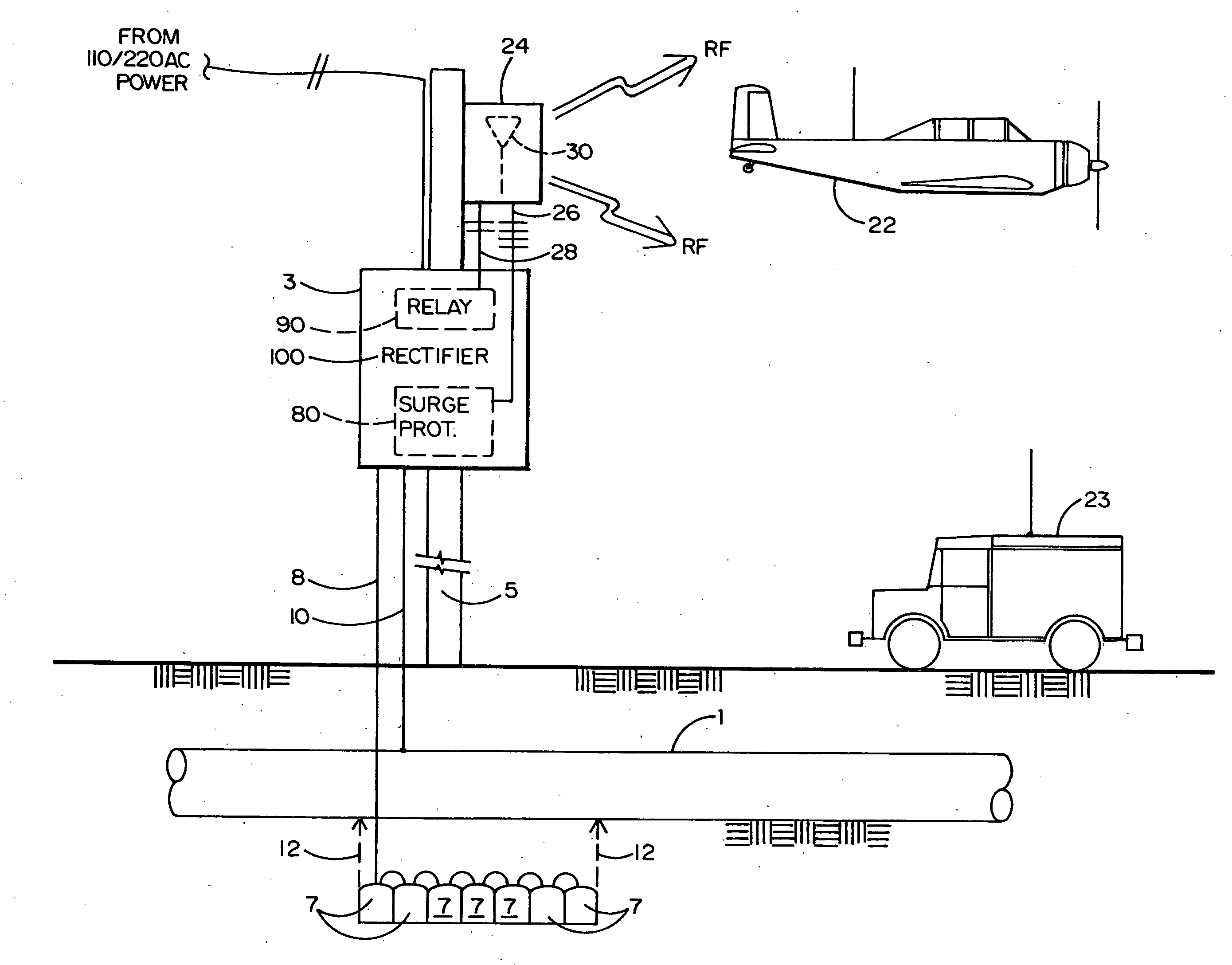
[0010]A low power transceiver of the cathodic protection monitor having a narrow beam antenna is connected to an I / O terminal of the CPU. Either a low flying airplane (which is regularly used to visually inspect the pipeline and / or the ground around the pipeline) or a motor vehicle driving near the cathodic protection rectifier can poll the CPU with a coded command signal that is transmitted to the CPU by way of the transceiver and its antenna. Once it is polled, the CPU will send a data packet containing its stored digitized current and voltage data for transmission back to the airplane or motor vehicle via the transceiver and antenna so that the data from all of the cathodic protection rectifiers along the pipeline can be efficiently collected for analysis by the pipe owner or maintenance crew to determine if any rectifier is in need of repair or replacement. By virtue of the foregoing, the time consuming and costly manual rectifier data collection technique, where a workman traditionally drives along the entire pipeline from one cathodic protection monitor to the next, is advantageously avoided.

Problems solved by technology

As will be explained in greater detail below, an underground natural gas, oil or water pipe or the tank in which such fluids flow or are stored and even an underwater bridge abutment is subject to chemical and electrically-induced corrosion, pitting and deterioration.
Such deterioration can lead to leakage which can contaminate the soil above the pipe or tank.
In some cases, an explosive condition can occur following pipe or tank erosion.
As a consequence of the foregoing, a hazardous environmental condition may be created which will necessitate an expensive cleanup and an interruption of the flow of fluid through the effected pipe.
Such a leak and flow interruption recently occurred in Alaska where metal pipes carrying oil were damaged by corrosion.
However, the chemical composition and moisture content of the soil in which a pipe or tank is buried often changes over time.
In other cases, the rectifier may not function properly or fail and be in need of repair or replacement.
A common technique for manually monitoring each of the series of pole-mounted rectifiers stationed along the pipeline is inefficient, time consuming, and correspondingly costly.

Method used


Image

  • Cathodic protection monitor
  • Cathodic protection monitor
  • Cathodic protection monitor

Examples


Embodiment Construction

[0020]Referring initially to FIG. 1 of the drawings, there is shown an underground metal pipe 1 of the type that carries natural gas, oil or water. However, the pipe 1 could also be an underground storage tank. Because of the acidity and composition of below ground dirt and water that surrounds pipe 1, the pipe (or tank) is known to experience rust and corrosion. Such rust and corrosion, if not prevented, can lead to a gradual erosion of the pipe and a subsequent leak of the fluid carried thereby. In the case where the fluid is oil, the resulting leakage can contaminate the ground adjacent the pipe leading to a potentially hazardous condition and an expensive cleanup operation.

[0021]One effective technique to combat corrosion of the pipe 1 is by means of cathodic protection. In general, a cathodic protection rectifier 100 is enclosed by a metallic casing 3 that is commonly mounted on a pole 5 (e.g., a telephone pole) that is staked in the ground near the pipe 1 to be protected. The ...


PUM


Abstract

A cathodic protection monitor is disclosed to be electrically connected to a cathodic protection rectifier that is adapted to prevent rust, corrosion and possible leakage in an underground pipe or storage tank above which the rectifier is supported. The cathodic protection monitor includes a CPU that reads, digitizes and stores analog current and voltage signals which are supplied from the DC output of the rectifier and are indicative of the effectiveness thereof. The monitor includes an ISM band transceiver and antenna by which the CPU is polled and from which packets of stored data are transmitted to a data collector at an overhead airplane or nearby motor vehicle for retransmission and analysis by the pipe owner or maintenance crew. Synchronized timing signals are supplied (from the National Bureau of Standards) to a stable auxiliary clock by way of a WWVB transceiver and antenna. The auxiliary clock from each of a plurality of cathodic protection monitors along the pipeline provides a synchronized clock control signal to a respective CPU which, in turn, generates a switched relay control signal to a relay of the cathodic protection rectifier. Accordingly, the relays of all of the cathodic protection rectifiers can be simultaneously energized and de-energized during successive time periods so that all of the cathodic protection rectifiers can be turned on and off at the same time as may be required to compile ground voltage readings along the pipeline as part of a government-mandated survey.

Description

BACKGROUND OF THE INVENTION[0001]1. Field of the Invention[0002]This invention relates to a cathodic protection monitor that is electrically connected to a conventional pole-mounted cathodic protection rectifier that is located above an underground oil, natural gas or water pipe (or storage tank) to reverse the effects of chemical and electrically-induced corrosion which are known to cause a potentially hazardous leak. The cathodic protection monitor receives analog current and voltage signals from the DC output terminals of the rectifier to be digitized, stored and transmitted (by antenna) on demand for analysis so that a determination can be made of the effectiveness of the rectifier and whether the rectifier is in need of repair or replacement.[0003]2. Background Art[0004]As will be explained in greater detail below, an underground natural gas, oil or water pipe or the tank in which such fluids flow or are stored and even an underwater bridge abutment is subject to chemical and e...

Claims


Application Information

Patent Timeline
IPC IPC(8): G08C17/00
CPCG08C19/02C23F13/04
Inventor PETERS, GEORGE W.
Owner OLEUMTECH CORP
Learn More