Method for operating an induction heating device

Active Publication Date: 2008-08-28
E G O ELEKTRO GERAETEBAU GMBH
View PDF28 Cites 19 Cited by
  • Summary
  • Abstract
  • Description
  • Claims
  • Application Information

AI Technical Summary

Benefits of technology

[0015]According to one embodiment of the invention, in a time interval prior to a zero passage of the alternating supply voltage, the intermediate circuit capacitor is discharged down to a threshold value through controlling a switching element, before the induction coil is controlled or activated, for generating an adjustable heating power or capacity, and during the discharge there is a limited heating power supplied to the optionally present cooking utensil. In one embodiment, the intermediate circuit capacitor is discharged in a predeterminable discharge time range prior to the zero passage of the alternating supply voltage. As a result of the intermediate circuit capacitor discharge, on starting a heating process, i.e. if the induction coil is to supply heating power to a cooking utensil, the intermediate circuit capacitor is substantially discharged. If at this time the switching element is switched through or becomes conductive, there is either no or only a limited pulse of current through the switching element and the resonant circuit of induction coil and capacitor. As a result there is no start-up noise and the pulsed current loading of the power components is reduced, so that their service life is increased. Following the discharge of the intermediate circuit capacitor the actual heating process can take place in the normal way, e.g. the switching element or elements can be controlled by a square-wave signal with an operating frequency and an associated operating duty cycle. Consequently the frequency converter is started with low currents or voltages in the zero passage area. With the rise of the half-wave following the zero passage, the converter can regulate to its operating point corresponding to the set heating power with an operating frequency and an operating duty cycle.
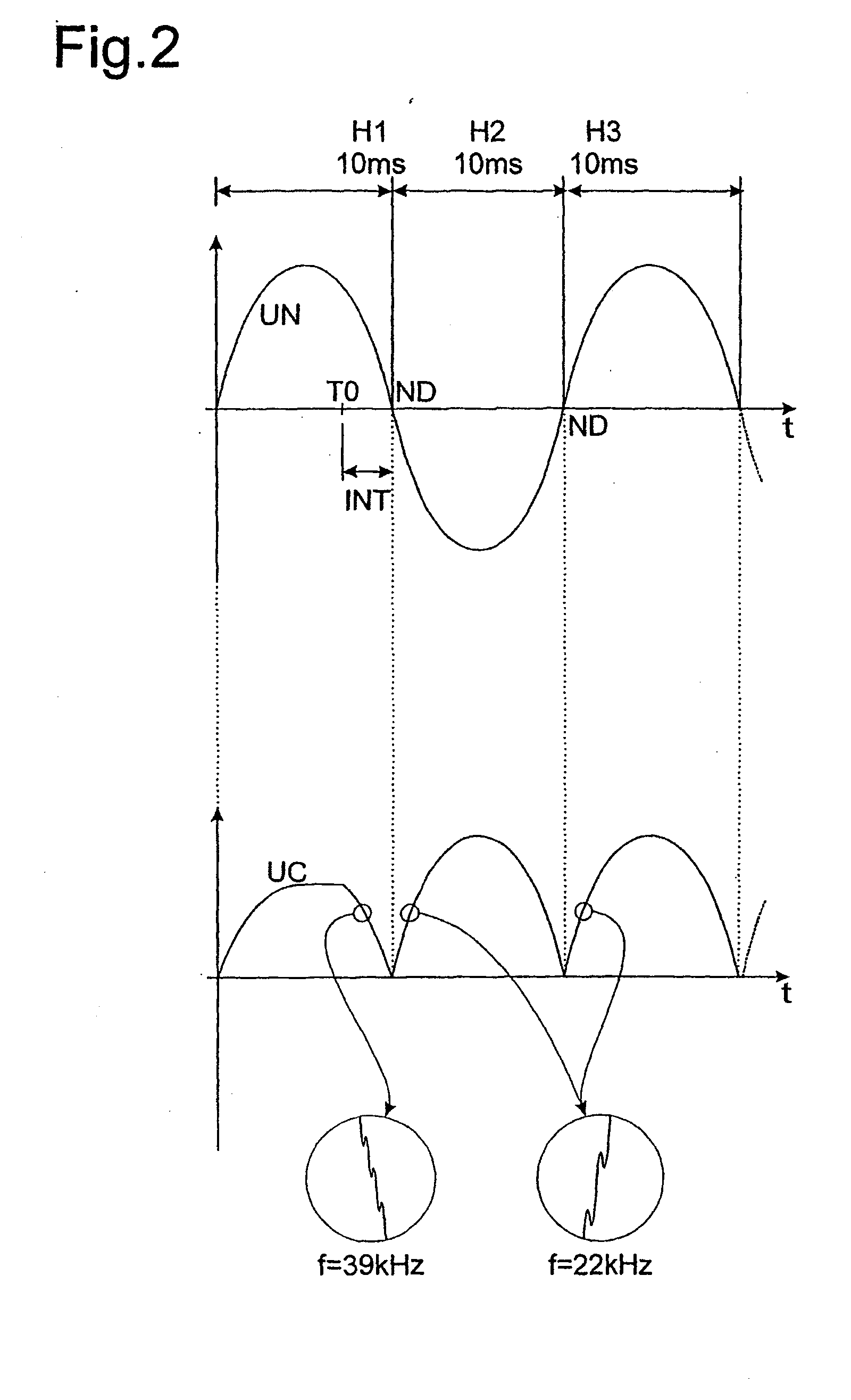
[0017]In a further embodiment the time range 1 to 5 ms, preferably 2.5 ms, begins prior to the zero passage of the alternating supply voltage. This allows a reliable discharge of the intermediate circuit capacitor, in the case of a comparatively limited power loss generation in the switching element through the discharge process.
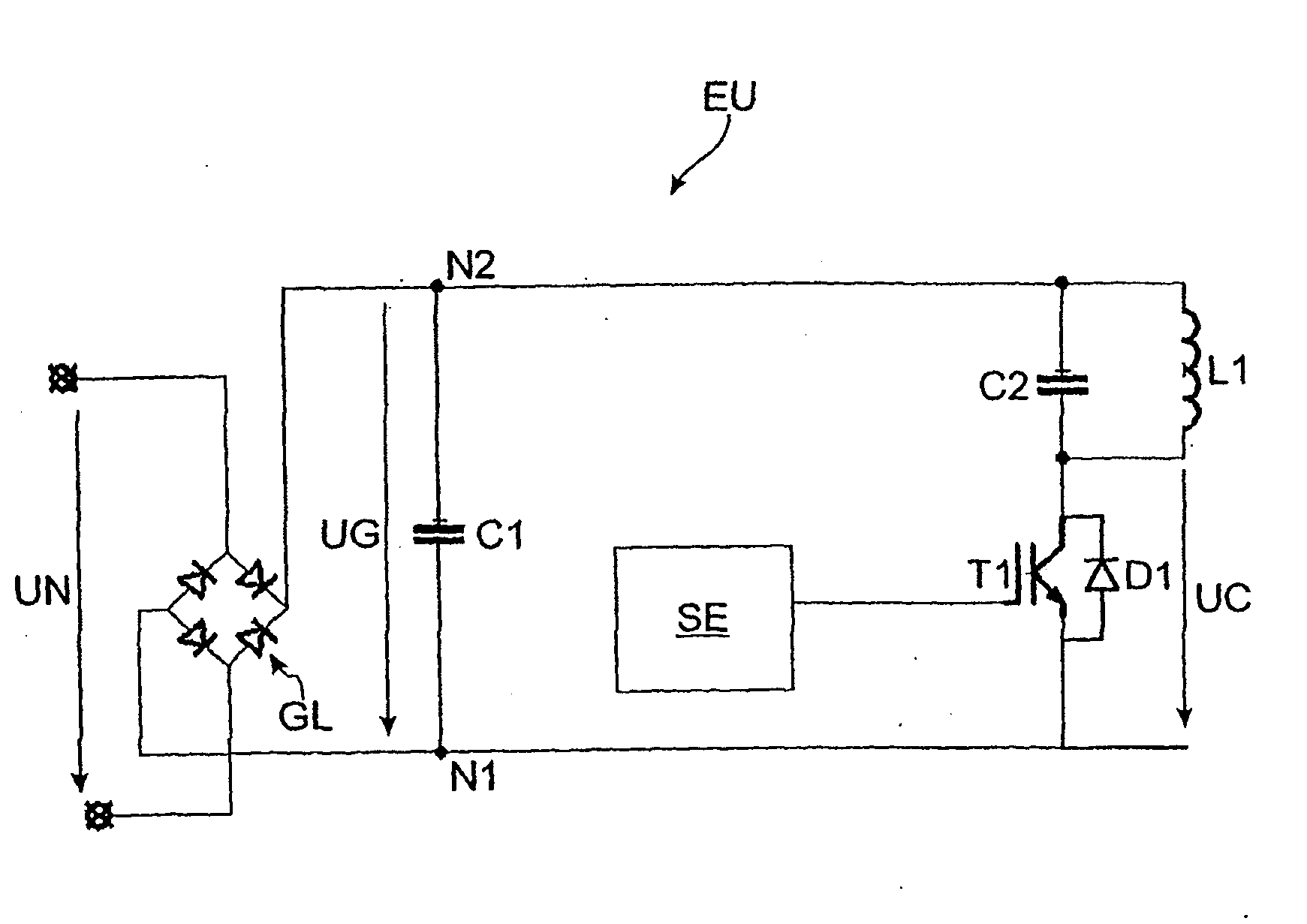
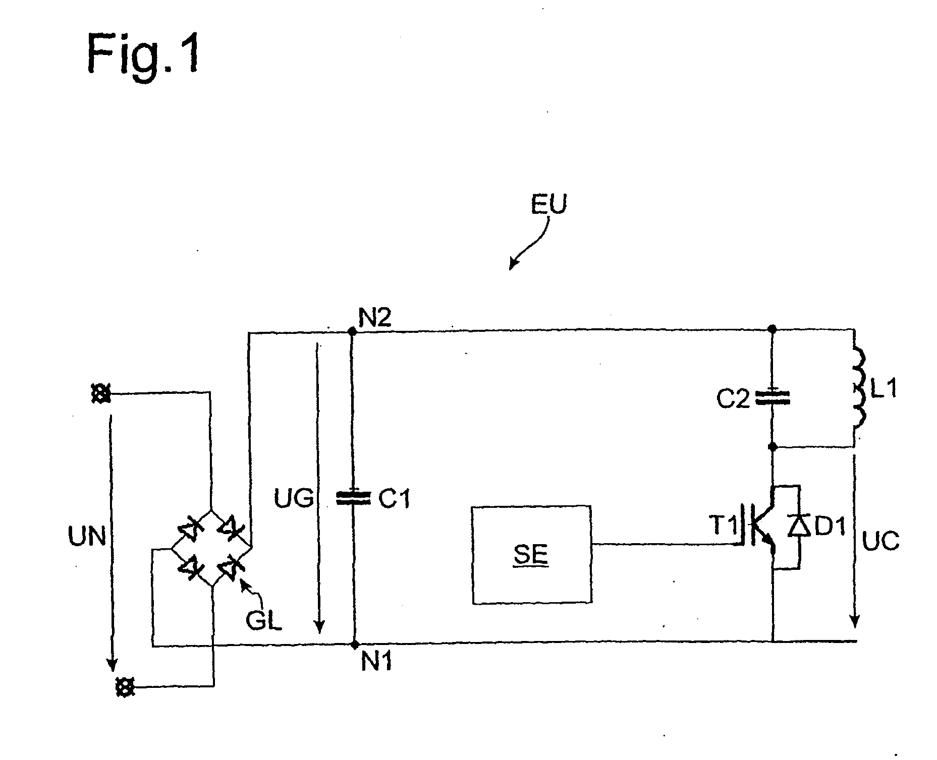
[0019]In a further embodiment the at least one switching element is a transistor, particularly an IGBT. For discharging the intermediate circuit capacitor, the transistor is preferably controlled during the discharge such that there is a linear transistor operating state. As in this mode or operating state the transistor does not completely switch through, the intermediate circuit capacitor is slowly discharged along the supply half-wave. The resulting currents through the parallel resonant circuit and the transistor remain comparatively low, so that noise evolution is avoided or significantly reduced.
[0021]In a further embodiment the adjustable heating power or capacity is generated with the aid of a half-wave pattern, the intermediate circuit capacitor being discharged prior to the activation of a half-wave. When the heating power is generated with the aid of the half-wave pattern, individual half-waves of the alternating supply voltage are completely extracted or deactivated, i.e. not used for heating power generation. In a so-called ⅓ supply half-wave operation, for example, only one of three successive half-waves is used or activated for feeding in power into the resonant circuit or induction coil. During the remaining two half-waves the switching element remains open, i.e. no power is fed into the resonant circuit. In a ⅔ supply half-wave operation two of three successive half-waves are used or activated for feeding power into the resonant circuit or induction coil. During an active half-wave, power adjustment takes place in the usual way. Supply half-wave operation permits a finer resolution of power stages over a considerable power adjustment range. Such a power adjustment is particularly advantageous for single transistor converters. If in the case of a conventional operating method of the single transistor converter, use is made of a half-wave operation for power adjustment, during an inactive half-wave, i.e. a half-wave during which no power is fed into the resonant circuit, there is a no-load voltage, e.g. 325 V in the case of a 230 V supply voltage, at the intermediate circuit capacitor.

Problems solved by technology

Both the full bridge and the half-bridge variant are comparatively expensive as a result of the large number of components required, particularly IGBTs.
This gives rise to an audible noise in a cooking utensil heated by the induction heating device, e.g. in the bottom of a saucepan.
There is also a reduction to the service life of components supplied with the high starting current.

Method used


Image

  • Method for operating an induction heating device
  • Method for operating an induction heating device
  • Method for operating an induction heating device

Examples


Embodiment Construction

[0029]FIG. 1 shows a circuit diagram of an induction heating device in the form of a single transistor converter EU. The induction heating device can also comprise further (not shown), identically constructed single transistor converters EU and additional conventional components, e.g. operating or control elements for adjusting the power level, etc.

[0030]The single transistor converter EU comprises a bridge rectifier GL, which generates an intermediate circuit direct voltage UG from the input alternating supply voltage UN of 230 V and 50 Hz, a buffer or intermediate circuit capacitor C1 for stabilizing or buffering the intermediate circuit direct voltage UG looped in between the output terminal N1 and N2 of rectifier GL, an induction coil L1 and a capacitor C2, which are connected in parallel and form a parallel resonant circuit, a controllable switching element in the form of an IGBT transistor T1, which is looped in series with the resonant circuit between the output terminals N1,...


PUM


Abstract

The invention relates to a method for operating an induction heating device. The induction heating device comprises an induction coil and a frequency converter for producing a control voltage for the induction coil. The frequency converter comprises a rectifier rectifying an alternating supply voltage (UN), an intermediate circuit capacitor, looped in between output terminals of the rectifier and equalizing the rectified voltage (UG), and at least one controllable switching element, looped in between the output terminals of the rectifier. According to the invention, in a predetermined discharge interval (INT) before a zero crossing (ND) of the alternating supply voltage (UN), the intermediate circuit capacitor is discharged to a threshold value by controlling the at least one switching element before the induction coil is controlled in order to produce an adjustable heating capacity.

Description

CROSS REFERENCE TO RELATED APPLICATIONS[0001]This application is a continuation of PCT / EP2006 / 009916, filed Oct. 13, 2006, which in turn claims priority to DE 10 2005 050 038.2, filed on Oct. 14, 2005, the contents of both of which are incorporated by reference.FIELD OF THE INVENTION[0002]The invention relates to a method for operating an induction heating device to produce an adjustable heating capacity.BACKGROUND OF THE INVENTION[0003]In induction heating devices an induction coil is supplied with an alternating voltage or an alternating current, so that in a cooking utensil coupled magnetically to the induction coil and which is to be heated, eddy currents are induced, which give rise to a heating of the utensil.[0004]Different circuit arrangements and control methods are known for controlling the induction coil. It is common to all the circuit and method variants that they generate a high frequency control or drive voltage for the induction coil from a low frequency input supply...

Claims


Application Information

Patent Timeline
IPC IPC(8): H05B6/06
CPCH05B6/062
Inventor SCHILLING, WILFRIEDDORWARTH, RALFVOLK, MARTINSCHONHERR, TOBIAS
Owner E G O ELEKTRO GERAETEBAU GMBH
Why Eureka
Try Eureka