
Power output device, and hybrid vehicle equipped with the power output device

a technology of power output device and hybrid vehicle, which is applied in special data processing applications, gas pressure propulsion mountings, toothed gearings, etc., can solve problems such as production of shift shocks (related art), and achieve the effect of avoiding shift shocks and restrainting the occurren

Inactive Publication Date: 2008-08-21
TOYOTA JIDOSHA KK
View PDF3 Cites 20 Cited by
  • Summary
  • Abstract
  • Description
  • Claims
  • Application Information

AI Technical Summary

Benefits of technology

[0023]The factors for occurrence of the aforementioned shift shock include a sudden change in the prime mover rotation speed during the driving control of the prime mover, an operation timing failure of a friction engagement device (e.g., a clutch or a brake that is hydraulically controlled) in the ratio shift control of the speed change mechanism, etc. Such factors arise conspicuously if the information about the prime mover rotation speed that is detected changes suddenly during a shifting operation of the speed change mechanism. Therefore, in the invention, in the case where the “gradient of change in the prime mover rotation speed is greater than or equal to a predetermined value”, which is a situation where the possibility of a sudden change of the prime mover rotation speed information is high, the foregoing switching is prohibited and the present prime mover rotation speed information continues to be adopted, so that the driving control of the prime mover and the ratio shift control of the speed change mechanism can be properly performed and therefore the shift shock can be avoided.
[0031]According to these features, too, in the case where the “difference between the prime mover rotation speed detected by the one rotation speed detector and the prime mover rotation speed detected by the other rotation speed detector is greater than or equal to a predetermined value”, which is a situation where the possibility of a sudden change of the prime mover rotation speed information is high, the switching operation is prohibited, and the present prime mover rotation speed information continues to be adopted, so that the shift shock can be avoided.
[0039]According to these features, too, in the case where the “difference between the gradient of change in the prime mover rotation speed detected by the one rotation speed detector and the gradient of change in the prime mover rotation speed detected by the other rotation speed detector is greater than or equal to a predetermined value”, which is a situation where the possibility of a sudden change of the prime mover rotation speed information is high, the switching operation is prohibited, and the present prime mover rotation speed information continues to be adopted, so that the shift shock can be avoided.
[0040]Even in a situation where the gradient of change in the prime mover rotation speed adopted as the present prime mover rotation speed information is large, the switching operation is permitted if the gradient of change in the prime mover rotation speed following the operation of switching the adopted information (the gradient of change in the prime mover rotation speed detected by the other rotation speed detector) is substantially as large as (is close to) the gradient of change in the prime mover rotation speed adopted as the present prime mover rotation speed information. Therefore, it is possible to restrain the occurrence of a situation in which the foregoing switching operation is frequently prohibited.
[0044]Thus, since the resolver and the north marker differ from each other in the principle in the detection of the rotation speed (differ in the transitional characteristic), a large shift shock may result if the foregoing switching operation is executed in the case where the shifting operation execution timing of the speed change mechanism and the execution-requiring timing for the switching operation (the operation of switching from the detected value from the resolver to the detected value from the north marker, or the operation of switching from the detected value from the north marker to the detected value from the resolver) substantially coincide with each other. Thus, according to the construction of the invention, while the highly accurate rotation speed detection operation suitable to rotation speeds is made possible by using the resolver and the north marker, the shift shock can be avoided by making proper the switching operation.
[0046]In the invention, in a construction in which the switching operation of selectively using values detected by a plurality of rotation speed detectors as the detected value of the prime mover rotation speed adopted as the information for executing controls and the like can be performed, the switching operation is prohibited in a specific condition. That is, the invention makes it possible to avoid a situation in which the prime mover rotation speed information suddenly changes during a ratio shifting operation. Therefore, the shift shock can be restrained, and good driveability can be realized in the case the power output device is mounted in a vehicle.

Problems solved by technology

That is, for example, in the case where the shifting operation execution timing of the speed change mechanism and the timing of transition of the rotation region substantially coincide, execution of the switching operation may result in a sudden change of the prime mover rotation speed information during the ratio shifting operation, leading to production of a shift shock (related art).

Method used


Image

  • Power output device, and hybrid vehicle equipped with the power output device
  • Power output device, and hybrid vehicle equipped with the power output device
  • Power output device, and hybrid vehicle equipped with the power output device

Examples


first embodiment

tion of Hybrid System

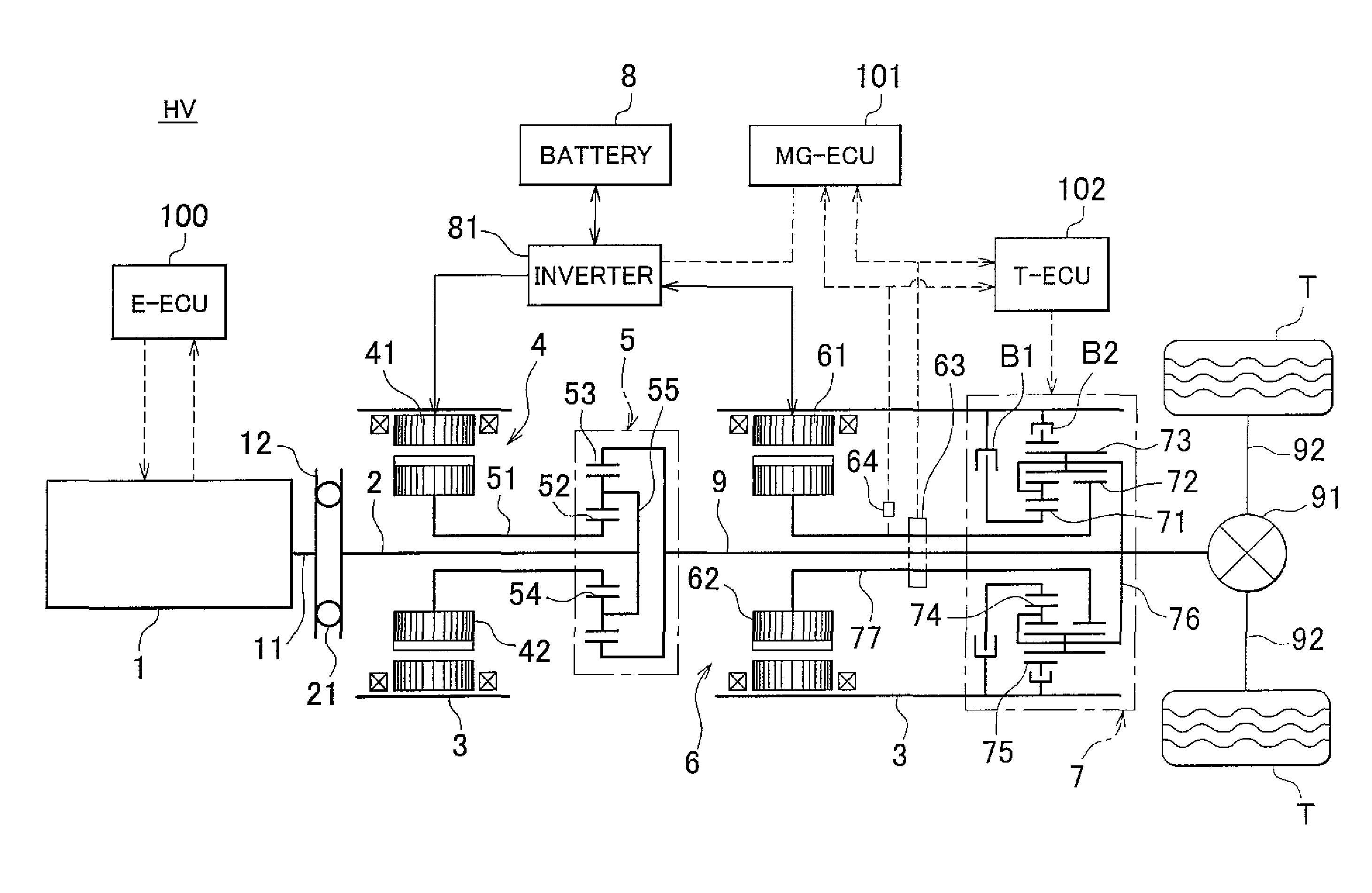
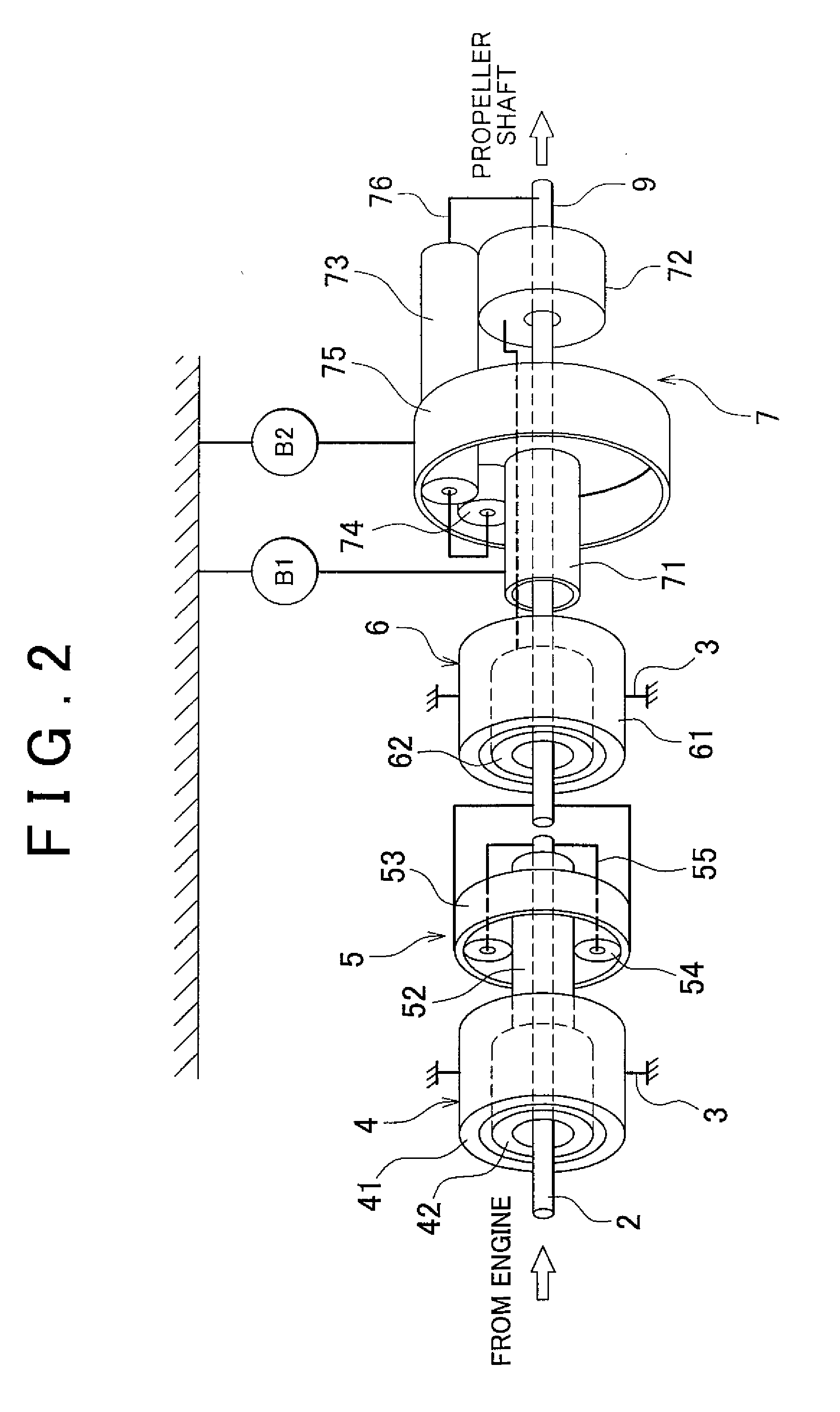
[0055]FIG. 1 is a diagram showing a general construction of a hybrid system mounted in a hybrid vehicle in accordance with of an embodiment. A vehicle HV shown in FIG. 1 is an FR type hybrid vehicle (hereinafter, simply referred to as “vehicle”). In FIG. 1, the vehicle HV is provided with an engine (internal combustion engine) 1 as a main drive force source. The engine 1 is a well known power device that burns a mixture of fuel and air in a cylinder, and converts thermal energy into rotational kinetic energy, and thus outputs the energy. FIG. 2 is a diagram schematically showing a gear train of the hybrid system.

[0056]Concretely, as the engine 1, it is possible to apply a gasoline engine, a diesel engine, an LPG engine, etc. The engine 1 is constructed so that the operation state thereof can be controlled via the degree of throttle opening (intake air amount), the amount of fuel injection, the ignition timing, etc. Besides, the control thereof is performed by an...

second embodiment

[0104]Next, a second embodiment of the invention will be described. The second embodiment is different from the first embodiment in the procedure for determining whether or not to prohibit the switching operation. Besides, the hybrid system in accordance with this embodiment has a plurality of kinds of feedback controls (the feedback control of the electric current supplied to the second motor-generator 6, and the feedback control of the engagement / release timing of the brakes B1, B2), and it is possible to switch among the feedback controls according to the running situation of the vehicle, and the like. The other constructions and operations of the hybrid system are the same as in the first embodiment, and therefore, only the feedback control operation and the operation of switching the detected rotation speed information will be described.

[0105]In the hybrid system in accordance with this embodiment, the number of the kinds of the feedback controls available is three, and the swi...


PUM


Abstract

A motor-generator is feedback-controlled by adopting the rotation speed information from a resolver when the rotation speed of a motor-generator is low, and by adopting the rotation speed information from a north marker when the rotation speed thereof is high. If the gradient of change in the rotation speed thereof based on the presently adopted rotation speed information is greater than or equal to a predetermined value, the rotation speed information switching operation is prohibited to prevent the shift shock during the ratio shifting operation of a reduction mechanism. That is, in a construction in which the rotation speed of the motor-generator can be detected via the resolver and the north marker, the power output device capable of properly performing the rotation speed control of the motor-generator and the like by making proper the timing at which the rotation speed information adopted for the control is switched.

Description

INCORPORATION BY REFERENCE[0001]The disclosure of Japanese Patent Application No. 2007-034542 filed on Feb. 15, 2007, including the specification, drawings and abstract is incorporated herein by reference in its entirety.BACKGROUND OF THE INVENTION[0002]1. Field of the Invention[0003]The invention relates to a power output device mounted in, for example, a hybrid vehicle that has a plurality of drive sources or the like, and a hybrid vehicle equipped with the power output device. In particular, the invention relates to an improvement in the timing of switching the rotation speed detector adopted to obtain rotation speed information for a driving control of a specific drive source (primer mover), or the like, from one to another of a plurality of rotation speed detectors that can detect the rotation speed of the drive source.[0004]2. Description of the Related Art[0005]A common hybrid drive device for vehicles employs an internal combustion engine, such as a gasoline engine, a diesel...

Claims


Application Information

Patent Timeline
Patent Type & Authority Applications(United States)
IPC IPC(8): B60W20/00H02P1/00F16H3/72G06F19/00H02P3/00B60K6/445B60K6/547B60L9/18B60L50/16B60W10/08B60W10/10
CPCB60K6/365Y10T477/23B60L2240/421B60W10/08B60W10/115B60W20/00B60W2510/081F16H3/728F16H2037/0873F16H2200/2007F16H2200/2023Y02T10/642Y02T10/6239Y10S903/945B60K6/445Y02T10/62Y02T10/64B60W2710/1038
Inventor MINAMIKAWA, KOKI
Owner TOYOTA JIDOSHA KK
Learn More