
Semiconductor device

a technology of semiconductor devices and semiconductors, applied in semiconductor devices, semiconductor/solid-state device details, printed circuits, etc., can solve problems such as radiation noise, disturbance of signal waveforms, and insufficient power supply, and achieve the effect of suppressing simultaneous switching nois

Active Publication Date: 2008-07-24
MICRON TECH INC
View PDF2 Cites 3 Cited by
  • Summary
  • Abstract
  • Description
  • Claims
  • Application Information

AI Technical Summary

Benefits of technology

[0010]The semiconductor device technology has been progressed by further increasing the operation speed and reducing the power consumption of the semiconductor devices. This has exposed various problems, which have not been considered as problems before, including problems relating signal integrity (SI) and power integrity (PI). The SI relates to a transmission waveform quality during signal transmission in a semiconductor device. The SI ensures that digital signals having wide frequency components are transmitted without deterioration and with the transmission waveform quality being kept high. The PI ensures that the quality of power supply is kept high. When the power supply is not stable, it will cause insufficient power supply to signals connected to the power supply, disturbance in signal waveform, and generation of radiation noise.
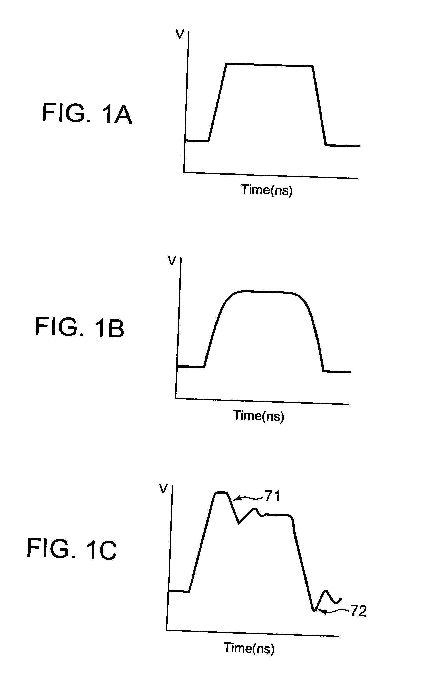
[0015]However, when the dielectric loss is too low, the behavior of the signal waveform becomes more notable, and the possibility is increased of occurrence of ringing (multiple reflections due to impedance mismatching occurring during connection of transmission lines or components) or overshoot and undershoot noise in signal wiring.
[0021]It is therefore an object of the present invention to provide a semiconductor device which is capable of effectively suppressing the simultaneous switching between the power supply and the ground and satisfying the requirements of signal integrity and power integrity even if not only power-supply and ground planes but also signal wiring are provided on a power supply layer or a ground layer.
[0026]According to the present invention, a semiconductor includes a substrate having a ground plane and a power-supply plane arranged to face each other with a dielectric layer interposed therebetween, the edge of the ground plane being offset from the edge of the power-supply plane in a direction orthogonal to a thickness direction. In the semiconductor device, a high dielectric loss tangent layer having a higher tan δ than the periphery is arranged in the dielectric layer between the edge of the ground plane and the edge of the power-supply plane in the direction orthogonal to the thickness direction, and the edge of the high dielectric loss tangent layer located outside with respect to the direction orthogonal to the thickness direction is positioned between the edge of the ground plane and the edge of the power-supply plane in the direction orthogonal to the thickness direction. This configuration makes it possible, even if signal wiring is located in the power supply layer or the ground layer, to efficiently suppress the simultaneous switching noise without attenuating signals propagated on the signal wiring, and to satisfy the requirements of signal integrity and power integrity.

Problems solved by technology

This has exposed various problems, which have not been considered as problems before, including problems relating signal integrity (SI) and power integrity (PI).
When the power supply is not stable, it will cause insufficient power supply to signals connected to the power supply, disturbance in signal waveform, and generation of radiation noise.
Signal deterioration is caused by various factors, one of which is attenuation of signal waveform due to dielectric loss between a signal and the ground.

Method used


Image

  • Semiconductor device
  • Semiconductor device
  • Semiconductor device

Examples


Embodiment Construction

[0043]A preferred embodiment of the present invention will be described with reference to the accompanying drawings.

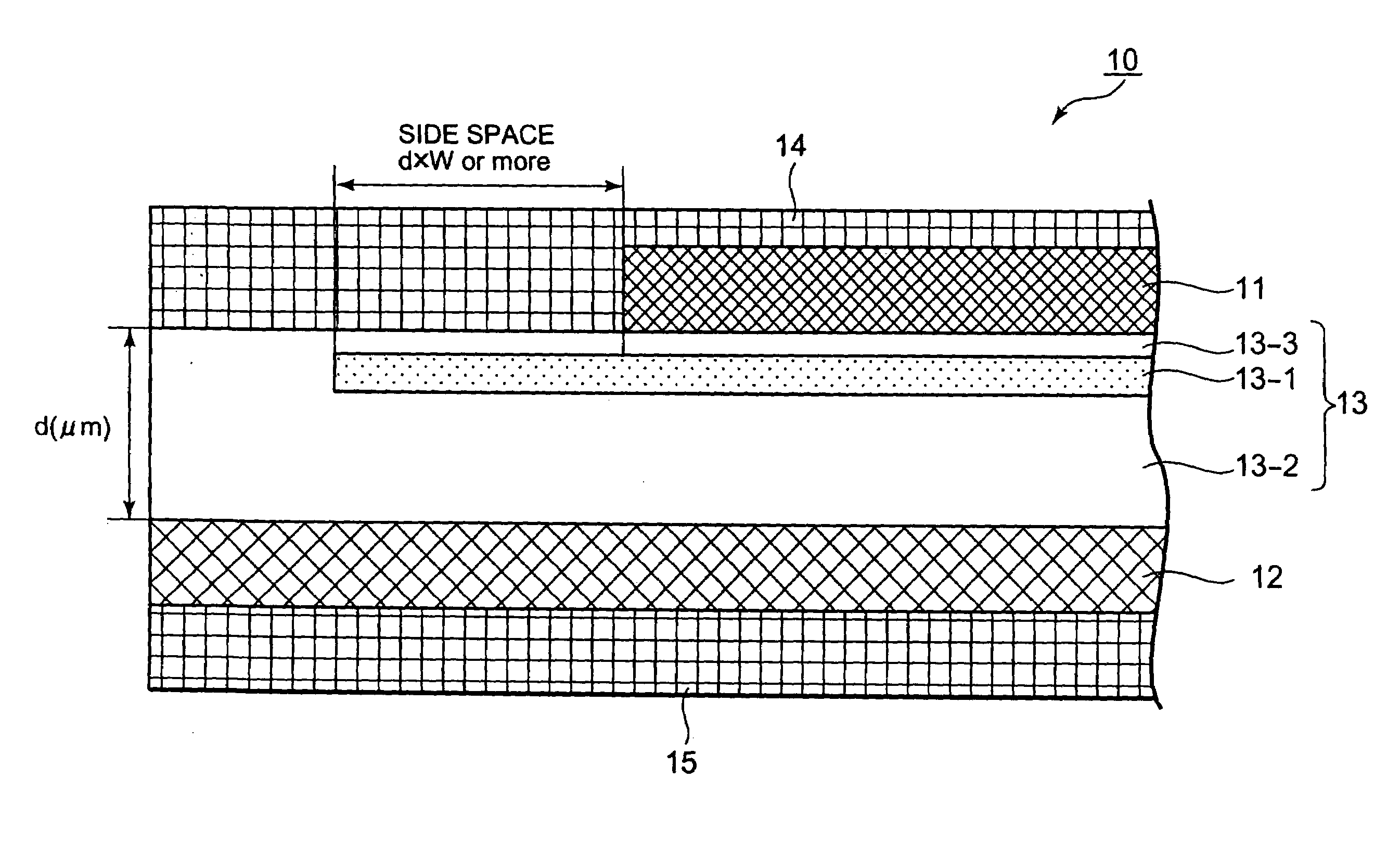
[0044]FIG. 4 is a partial cross-sectional view showing a structure of a substrate 10 for use in a semiconductor device according to an embodiment of the present invention.

[0045]As shown in FIG. 4, a power-supply plane (power supply layer) 11 and a ground plane (GND layer) 12 are arranged to face each other across a dielectric layer 13. The power-supply plane 11 and the ground plane 12 are made of copper (Cu), for example, and their surfaces are covered with solder resist layers 14 and 15, respectively.

[0046]The plan shape (a shape as viewed from above) of the ground plane 12 is rectangular, for example. Unlike the ground plane 12, the power-supply plane 11 has an island-like or complicated shape with slits or the like. Therefore, the edge of the power-supply plane 11 is located on the inner side (right side in the drawing) than the edge of the ground plane 12 in a dire...


PUM


Abstract

A high dielectric loss tangent layer is provided in a dielectric layer between a power-supply plane and a ground plane. The high dielectric loss tangent layer is arranged such that its edge is located between the edge of the power-supply plane and the edge of the ground plane. The edge of the high dielectric loss tangent layer is preferably separated by a predetermined distance or more from the edge of the power-supply plane or the edge of the ground plane which is located on the inner side.

Description

[0001]This application is based upon and claims the benefit of priority from Japanese patent application No. 2007-009802, filed on Jan. 19, 2007, the disclosure of which is incorporated herein in its entirety by reference.BACKGROUND OF THE INVENTION[0002]1. Field of the Invention[0003]The present invention relates to a semiconductor device, and in particular to a semiconductor device provided with a mounting board or a package substrate having a power-supply plane, a ground plane, and a dielectric layer disposed therebetween.[0004]2. Description of the Related Art[0005]Following recent increase in operation speed and reduction in power consumption of semiconductor devices, noise generated between the power supply and the ground of the mounting board or package substrate increases its effect on transmission of signals.[0006]Simultaneous switching noise is referred to as an example of the noise generated between the power supply and the ground. The simultaneous switching noise has con...

Claims


Application Information

Patent Timeline
IPC IPC(8): H01L23/48
CPCH01L23/50H01L2924/01033H01L24/50H01L2924/01013H01L2924/01027H01L2924/01029H01L2924/01074H01L2924/01082H01L2924/04953H01L2924/19041H01L2924/30105H01L2924/3011H01L2924/01005H01L2924/01006H01L24/32
Inventor KOSHIISHI, KAZUTAKAKATAGIRI, MITSUAKIISA, SATOSHI
Owner MICRON TECH INC
Learn More