Optical recording medium

Inactive Publication Date: 2008-07-17
TDK CORPARATION
View PDF32 Cites 5 Cited by
  • Summary
  • Abstract
  • Description
  • Claims
  • Application Information

AI Technical Summary

Benefits of technology

[0021]Furthermore, since the extinction coefficient of the recording film is 0.4 or less, the ratio of the amount of light absorption in the recording film to that in the information layer as a whole is small. Therefore, the effect of suppressing the changes in the optical properties of the information layer is high. Even when the amount of light absorption in the recording film is small, the light absorbing film absorbs light so that the light for forming good recording marks in the recording film can be absorbed in the information layer as a whole. As the extinction coefficient of the recording film increases, the thickness of the light absorbing film must be increased correspondingly in order to ensure that the effect of the light absorbing film is retained. When the extinction coefficient of the recording film is excessively large, the thickness of the light absorbing film must be increased to an extent that is not easily attainable in a practical design. However, since the extinction coefficient of the recording film is 0.4 or less, a suitable light absorbing film is easily designed.
[0022]In addition to this, when the extinction coefficient of the light absorbing film is excessively large, the variations in the amount of light absorption caused by variations in the thickness of the light absorbing film can be significantly large. Therefore, the light absorbing film must be deposited to a desirable thickness with high precision and it may, in practice, be difficult to deposit such a light absorbing film. However, since the extinction coefficient of the light absorbing film is 1.5 or less, a suitable light absorbing film can be easily deposited.
[0027]According to the present invention, a reliable optical recording medium can be provided which includes an information layer exhibiting small changes in the optical properties even during long-term storage.

Problems solved by technology

However, the inventors have recognized that it is difficult to develop a recording film material which exhibits sufficient changes in its optical properties even when a blue or blue-violet laser beam is used as the irradiation light beam and which also exhibits only small changes in its optical properties even during long-term storage.

Method used


Image

  • Optical recording medium
  • Optical recording medium
  • Optical recording medium

Examples


working example 1

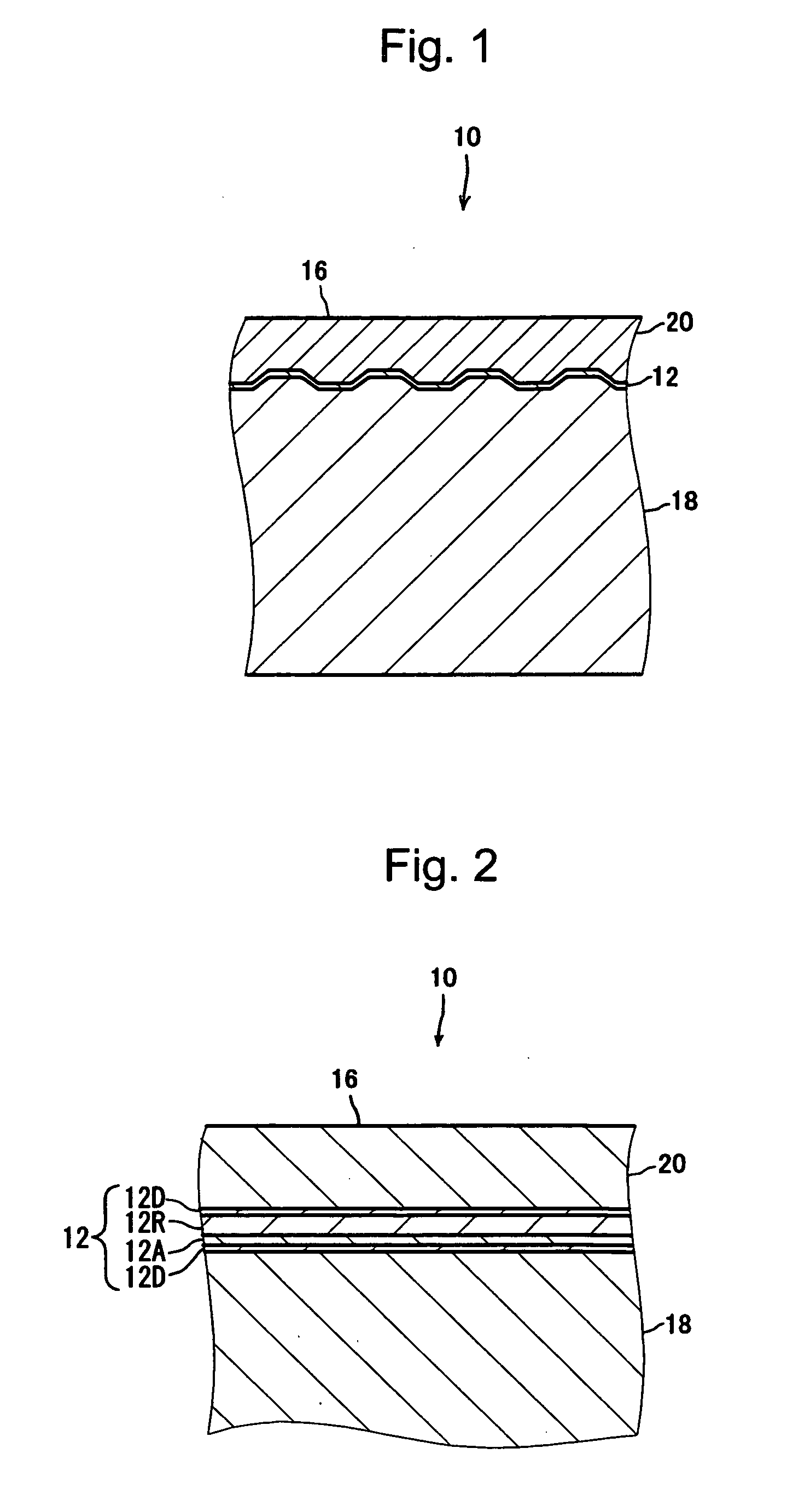
[0066]Samples A to D each having a configuration the same as that of the optical recording medium 10 of the first exemplary embodiment were manufactured. The configuration of the information layer 12 of each of the samples A to D is shown in Table 1. In each of the samples A to D, the thickness of the substrate 18 was 1.1 mm, and the thickness of the cover layer 20 was 100 μm.

TABLE 1Light absorbing filmRecording filmDielectric filmExtinctionExtinctionExtinctionThicknesscoefficientThicknesscoefficientThicknessSampleMaterialcoefficient(nm)MaterialkAtA(nm)MaterialkRtR(nm)ATiO20.055Fe2O30.85Bi:Fe:O = 25:5:700.2838BTiO20.055Fe2O30.85Bi:Ge:O = 28:2:700.1838CTiO20.055Fe2O30.85Bi:Ge:O = 21:10:690.0838DTiO20.055V2O50.58Bi:Ge:O = 21:10:690.0838Before hightemperatureand highAfter highhumiditytemperaturetreatmentand high humidityDielectric filmOptimaltreatmentExtinctionThicknessKA × tAKR × tR(kA × tA) / recordingJitterRecording powerJitterSampleMaterialcoefficient(nm)(nm)(nm)(kR × kR)power (mW)(%...

working example 2

[0070]Samples E to H were manufactured. In contrast to the optical recording medium 10 of the first exemplary embodiment, in the configuration of each of the samples E to H, a dielectric film was formed between the light absorbing film 12A and the recording film 12R. The dielectric film had an extinction coefficient which is less than that of the recording film 12R. The configuration of the information layer 12 of each of the samples E to H is shown in Table 2. The other components of each of the samples E to H are the same as those of each of the samples A to D of Working Example 1.

TABLE 2Light absorbing filmDielectric filmExtinctionDielectric filmExtinctionThicknesscoefficientThicknessExtinctionThicknessRecording filmSampleMaterialcoefficient(nm)MaterialkAtA(nm)Materialcoefficient(nm)MaterialETiO20.055Fe2O30.85TiO20.055Bi:Ge:O = 21:10:69FTiO20.055Fe2O30.85TiO20.055Bi:Sb:O = 21:11:68GTiO20.055Fe2O30.85TiO20.055Bi:Mg:O = 20:11:69HTiO20.055Al72Cr9O111.43TiO20.055Bi:Ge:O = 21:10:69Bef...

working example 3

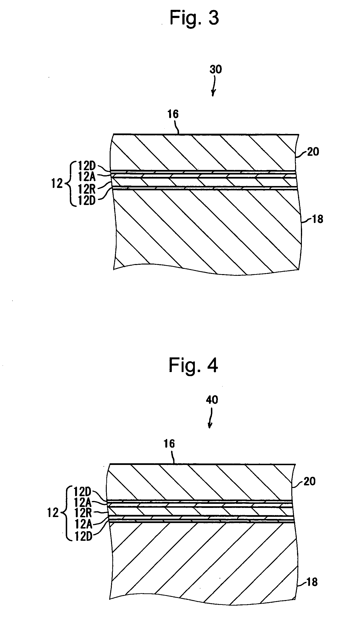
[0073]Sample J of the optical recording medium having a configuration which was the same as that of the optical recording medium 30 of the second exemplary embodiment was manufactured. The configuration of the information layer 12 of the sample J is shown in Table 3. The other components are the same as those of each of samples A to D of Working Example 1.

TABLE 3Recording filmLight absorbing filmDielectric filmExtinctionExtinctionExtinctionThicknesscoefficientThicknesscoefficientThicknessSampleMaterialcoefficient(nm)MaterialkRtR(nm)MaterialkAtA(nm)JTiO20.055Bi:Ge:O = 21:10:690.0838Fe2O30.85Before hightemperatureand highAfter highhumiditytemperature andtreatmenthigh humidityDielectric filmOptimaltreatmentExtinctionThicknessKA × tAKR × tR(kA × tA) / recordingJitterRecording powerJitterSampleMaterialcoefficient(nm)(nm)(nm)(kR × kR)power (mW)(%)(mW)(%)JTiO20.05104.003.041.325.55.35.55.8

[0074]As in Working Example 1, the optimal recording power and jitter of the samples J were measured bef...


PUM


Abstract

A reliable optical recording medium is provided which includes an information layer exhibiting small changes in the optical properties even during long-term storage. The optical recording medium includes the information layer including a recording film having an extinction coefficient of 0.4 or less at the wavelength of a laser beam used for recording and reproducing. The information layer further includes a light absorbing film having an extinction coefficient of 1.5 or less at the wavelength of the laser beam, and the extinction coefficient of the light absorbing film is greater than that of the recording film.

Description

BACKGROUND OF THE INVENTION[0001]1. Field of the Invention[0002]The present invention relates to an optical recording medium in which a blue or blue-violet laser beam is used for recording and reproducing.[0003]2. Description of the Related Art[0004]Optical recording media such as CDs (Compact Discs) and DVDs (Digital Versatile Discs) have been widely utilized as information recording media. In addition, in recent years, the use of optical recording media known as Blu-ray Discs (registered trademark) and HD DVDs (registered trademark) has become widespread. In such optical recording media, a blue or blue-violet laser beam having a wavelength of 405 nm (within the range of 375 to 435 nm) is used for recording and reproducing, so that a larger amount of information can be recorded in comparison to conventional media. Note that, in such optical recording media, tracks are formed with a track pitch within the range of 0.1 to 0.5 μm, and more specifically, with a track pitch of 0.32 μm f...

Claims


Application Information

Patent Timeline
IPC IPC(8): G11B7/00G11B7/24G11B7/24035G11B7/24067G11B7/24076G11B7/24085G11B7/243G11B7/2433G11B7/254G11B7/257
CPCG11B7/24035G11B7/24067G11B7/24079G11B7/259G11B2007/24304G11B2007/25715G11B2007/24314G11B2007/2432G11B2007/25706G11B2007/25708G11B2007/24306
Inventor MISHIMA, KOJIKIKUKAWA, TAKASHIITOH, HIDETAKE
Owner TDK CORPARATION
Why Eureka
Try Eureka