
Electric power pack that includes a fuel cell

a fuel cell and electric power pack technology, applied in the field of fuel cells, can solve the problems of poor cell efficiency, high cost, and high cost of fuel cells, and achieve the effect of high level of autonomy

Inactive Publication Date: 2008-07-03
MICHELIN RECH & TECH SA
View PDF7 Cites 11 Cited by
  • Summary
  • Abstract
  • Description
  • Claims
  • Application Information

AI Technical Summary

Benefits of technology

"The present invention is about a fuel cell that operates with oxygen gas obtained by separating nitrogen from ambient air on board a vehicle. The fuel cell comprises a stack of individual cells, each containing a cathode and an anode. The system includes an electronic traction motor supplied by the fuel cell, and a device for delivering fuel to the fuel cell. The invention also includes a separator for separating the components of air, an air compressor, and a system for supplying oxidizer gas to the fuel cell. The invention aims to provide a lightweight and efficient solution for supplying power to electric traction vehicles."

Problems solved by technology

However, it suffers from the fact that the efficiency of the fuel cell supplied with air is lower than that obtained with pure oxygen.
This means that, for the same useful power, a much heavier and more bulky cell has to be provided in the case in which the supply is carried out directly from the ambient air than in the case of supply with pure oxygen.
Of course, the reverse problem is encountered with pure-oxygen supplies, namely the fact that the better efficiency of the cell is counteracted by the need to supply pure oxygen on board the vehicle.

Method used


Image

  • Electric power pack that includes a fuel cell
  • Electric power pack that includes a fuel cell
  • Electric power pack that includes a fuel cell

Examples


examples

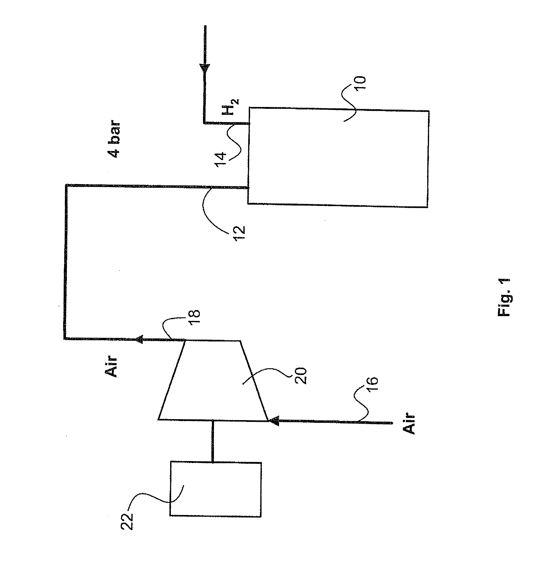
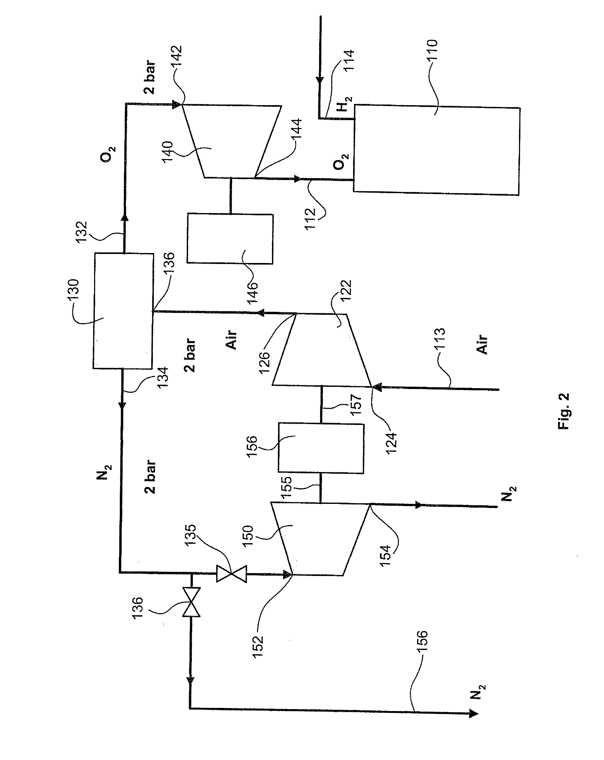
[0048]A supply system according to the invention, given as an example for a 30 kW fuel cell, comprises a stack of 107 individual cell elements each comprising a solid electrolyte polymer membrane with a thickness of about 50 microns and an area of 300 cm2. The cell elements can operate at a temperature of 70° C. at a pressure of 4 bar absolute in order to deliver power of about 280 watts at a current of 360 amps. For this power, the fuel cell requires 269 liters of hydrogen per minute and 135 liters of oxygen per minute. In fact, the oxygen flow rate in this example is 155 liters per minute, i.e. about 15% higher than the theoretical requirement. The operating factors specific to the construction of the fuel cell and to the other functions of the oxidizer gas stream, which were mentioned previously in regard to FIG. 1, explain this difference.

[0049]It was seen that the oxygen carrier gas was delivered to the inlet 112 of the fuel cell at a pressure of 4 bar absolute by the high-pres...


PUM

PropertyMeasurementUnit
pressureaaaaaaaaaa
pressureaaaaaaaaaa
inlet pressureaaaaaaaaaa

Abstract

To improve the way in which a fuel cell is installed, especially in the case of fuel cells on board electric traction vehicles, the oxygen needed for supplying the fuel cell is produced in situ by separating the nitrogen from the ambient air continuously, without a change of state. Thus, an electric power pack comprises a stack of electrochemical cell elements each possessing a cathode and an anode, in electrochemical coupling relationship with an electrolyte, and an electrical output circuit suitable for connecting the cathode and the anode through a load, a device for delivering fuel to the anode and an on-board oxygen generator based on a separator, for separating the oxygen and nitrogen of the ambient air without a change of state, in order to supply the cathode of said cell elements. According to a preferred embodiment, the separator is of the nitrogen pressure swing adsorption type. In one embodiment, the separator is supplied with compressed air by a first compressor and the oxygen delivered at its output is compressed further in order to supply the fuel cell. The whole assembly makes it possible to achieve an improved performance compromise for vehicle applications in which great autonomy is required.

Description

BACKGROUND OF THE INVENTION[0001]1. Field of the Invention[0002]The present invention relates to fuel cells, especially cells installed on board electric traction vehicles to generate the necessary current directly from an on-board fuel supply.[0003]2. Prior Art[0004]It is known that fuel cells produce electrical energy by an electrochemical oxidation-reduction reaction starting from hydrogen or another reducing material (the fuel) and oxygen (the oxidizer), without passing via conversion to mechanical energy. This technology seems promising for applications in the transport field of whatever nature, especially in motor vehicles.[0005]A fuel cell comprises in general the series connection of individual cell elements, each essentially comprising an anode and a cathode coupled together in electrical conduction relationship by an electrolyte. One type of electrolyte that is very suitable for example for motor vehicle applications is a solid electrolyte essentially consisting of a polym...

Claims


Application Information

Patent Timeline
Patent Type & Authority Applications(United States)
IPC IPC(8): H01M8/02B01D53/047
CPCH01M8/00H01M8/0662Y02T90/32H01M2250/20Y02E60/50H01M8/0687Y02T90/40
Inventor DELFINO, ANTONIO
Owner MICHELIN RECH & TECH SA
Learn More