
Sorting Recycled Materials With Automatically Adjustable Separator Using Upstream Feedback

a technology of automatic adjustment and separator, which is applied in the direction of gas current separation, sustainable waste treatment, instruments, etc., can solve the problems of only good setting for a matter, low and limited mrf operators' ability to determine the optimal operating parameters of these new screens. achieve the effect of improving the efficiency of separator operation

Inactive Publication Date: 2008-07-03
KABUSHIKI KAISHA MSS
View PDF25 Cites 14 Cited by
  • Summary
  • Abstract
  • Description
  • Claims
  • Application Information

AI Technical Summary

Benefits of technology

[0026](e) adjusting said plurality of adjustable machine operating parameters, via a computerized control system, in response to said sensed present value of said characteristic of said input stream so that said adjustable machine operating parameters approach said historical values of the adjustable machine operating parameters corresponding to improved quality of separation for said sensed present value of said characteristic of said input stream.
[0029]Another object of the present invention to provide improved methods of adjusting the operation of an adjustable separator based upon the density of an incoming material stream.
[0031]Still another object of the present invention is the provision of methods and systems for continuously monitoring and adjusting the operation of a material separator to improve the efficiency of operation of the separator.

Problems solved by technology

Unfortunately, however, very few MRF operators are capable of determining the optimum operating parameters for these new screens.
Experience in MRFs also shows that even when the screens are properly set for a certain mixture of recyclables and moisture content, that setting is only good for a matter of a few minutes as the composition and moisture content changes.
Even when set optimally the screens are not 100% effective.

Method used


Image

  • Sorting Recycled Materials With Automatically Adjustable Separator Using Upstream Feedback
  • Sorting Recycled Materials With Automatically Adjustable Separator Using Upstream Feedback
  • Sorting Recycled Materials With Automatically Adjustable Separator Using Upstream Feedback

Examples


Embodiment Construction

The Overall MRF System

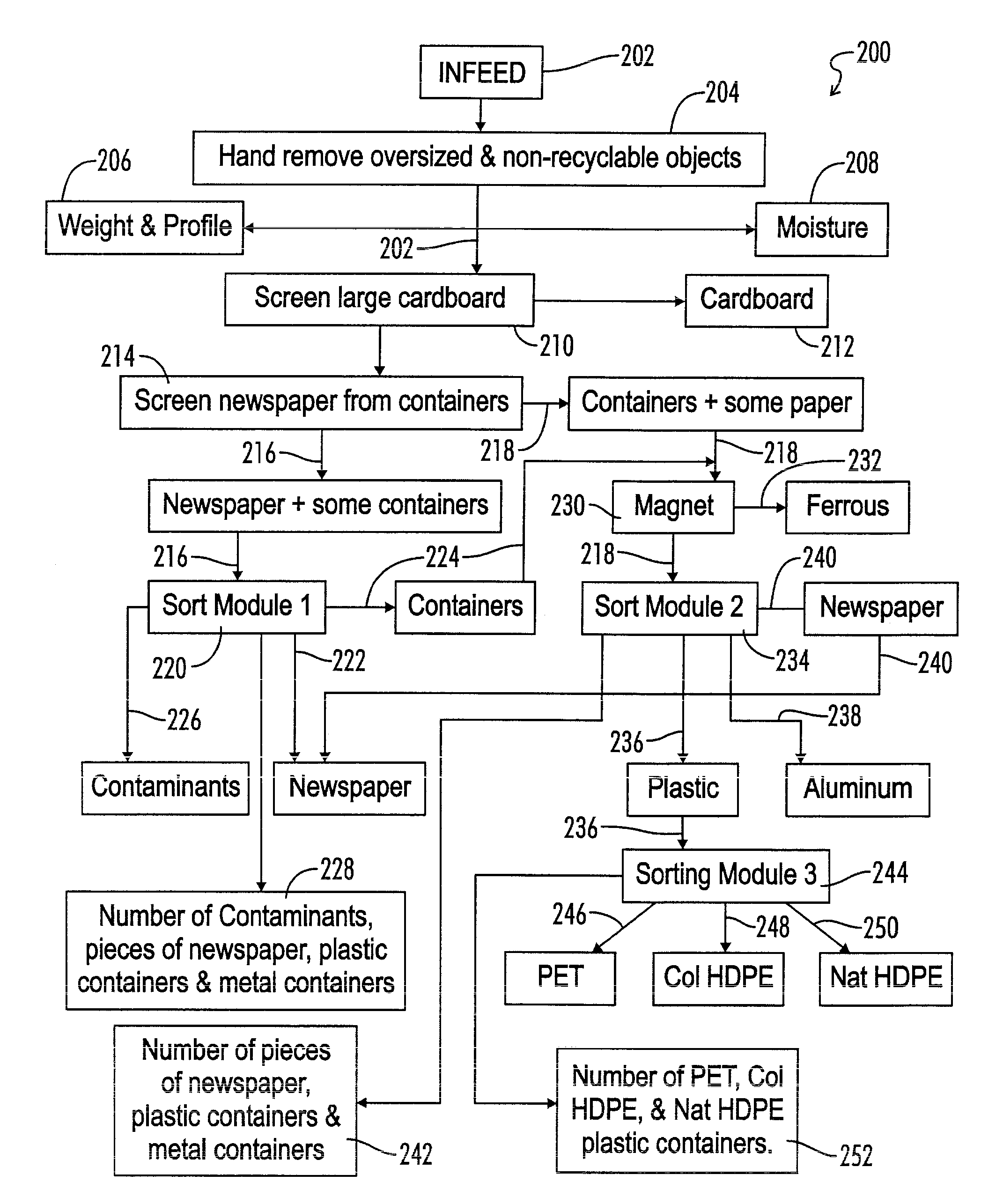
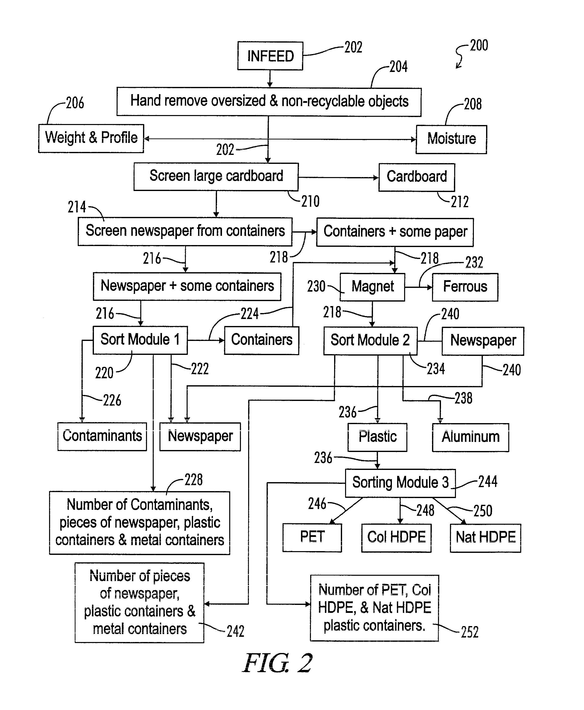
[0045]Referring now to FIG. 2, the Materials Recovery Facility (MRF) of the present invention is shown and generally designated by the numeral 200. FIG. 2 schematically illustrates the major components of and the material flow through the Materials Recovery Facility 200.

[0046]An input waste material stream 202 enters the MRF 200. As indicated at block 204, oversized and non-recyclable objects are removed by hand.

[0047]A weight and profile sensor 206 and a moisture sensor 208 are provided to monitor the weight, the height profile and the moisture content of the input material stream 202.

[0048]As indicated at block 210 a large article screening device 210 may be used to separate large cardboard items which go to a cardboard destination 212.

[0049]The bulk of the material which is typically made up of containers of various types and newspaper goes to a mechanical screening device 214 which may, for example, be an adjustable angle trough shape screening device such ...


PUM

PropertyMeasurementUnit
angleaaaaaaaaaa
frequencyaaaaaaaaaa
densityaaaaaaaaaa

Abstract

Methods and systems are provided for controlling an automatic separator apparatus of a Materials Recovery Facility. The separator apparatus has a plurality of adjustable machine operating parameters. An input stream of recycled materials is provided, wherein the composition of the input stream is subject to variation during a time interval. Historical data is provided representative of a set of historical values of the operating parameters corresponding to improved quality of separation for given values of a characteristic of the input stream. A present value of the characteristic of the input stream is sensed. A plurality of machine operating parameters is automatically adjusted in response to the sensed present value of the characteristic.

Description

[0001]This application is a divisional application of U.S. patent application Ser. No. 11 / 194,708, filed Aug. 1, 2005, entitled “Sorting Recycled Materials With Automatically Adjustable Separator Using Upstream Feedback”, which parent application claims benefit of U.S. Provisional Patent Application No. 60 / 600,206, filed Aug. 10, 2004, entitled “Materials Recovery Facility Process Optimization Via Unit Operation Feedback”, the details of both of which are incorporated herein by reference.[0002]This is a Utility Patent Application filed by Garry R. Kenny, a citizen of the United States, residing in West Linn, OR 97068, in an invention entitled “Sorting Recycled Materials With Automatically Adjustable Separator Using Upstream Feedback”BACKGROUND OF THE INVENTION[0003]1. Field of the Invention[0004]The present invention relates generally to the field of sorting of recycled materials, and more particularly, but not by way of limitation, to methods and apparatus for optimizing the operat...

Claims


Application Information

Patent Timeline
Patent Type & Authority Applications(United States)
IPC IPC(8): B07C5/34
CPCB03B9/06B07B1/15B07B4/08B07B9/02B07B11/04G06Q10/30B07B13/08B07B13/18B07C5/00D21B1/028G06Q10/06B07B13/00Y10S209/93Y02W30/52Y02W90/00
Inventor KENNY, GARRY R.
Owner KABUSHIKI KAISHA MSS
Learn More