Instrumented rolling bearing device

Inactive Publication Date: 2008-06-26
AB SKF
View PDF99 Cites 31 Cited by
  • Summary
  • Abstract
  • Description
  • Claims
  • Application Information

AI Technical Summary

Benefits of technology

[0007]In an embodiment, a speed sensor device supplies a signal that is precise and stable over time in a very small axial space requirement and for a reasonable cost.
[0009]The fact that the electronic circuit board is pliable makes it possible to precisely adjust the zone of the board supporting the sensor on the reference surface, hence a precise positioning of the sensor. In addition, the arrangement of the sensor on the flat portion of the board makes it possible to obtain a precise and sound positioning. This provides a sensor supplying a signal that is precise and stable over time.
[0024]The sensor is capable of supplying a signal that is precise, reliable and stable over time and of doing so with a reduced axial space requirement and a low cost.

Problems solved by technology

In this case, certain technical points are difficult.
The sensor must be positioned radially with great precision relative to the coder, which is difficult and assumes that the sensor rests on a reference surface itself positioned with precision relative to the coder.
It is often necessary to have recourse to resin attachment of the sensor on its support to hold it in the appropriate position, which is a costly operation.
Here again, these operations are costly.
This type of sensor of the inductive type does not provide a sufficiently powerful and precise signal to suit all industrial applications.

Method used


Image

  • Instrumented rolling bearing device
  • Instrumented rolling bearing device
  • Instrumented rolling bearing device

Examples


Embodiment Construction

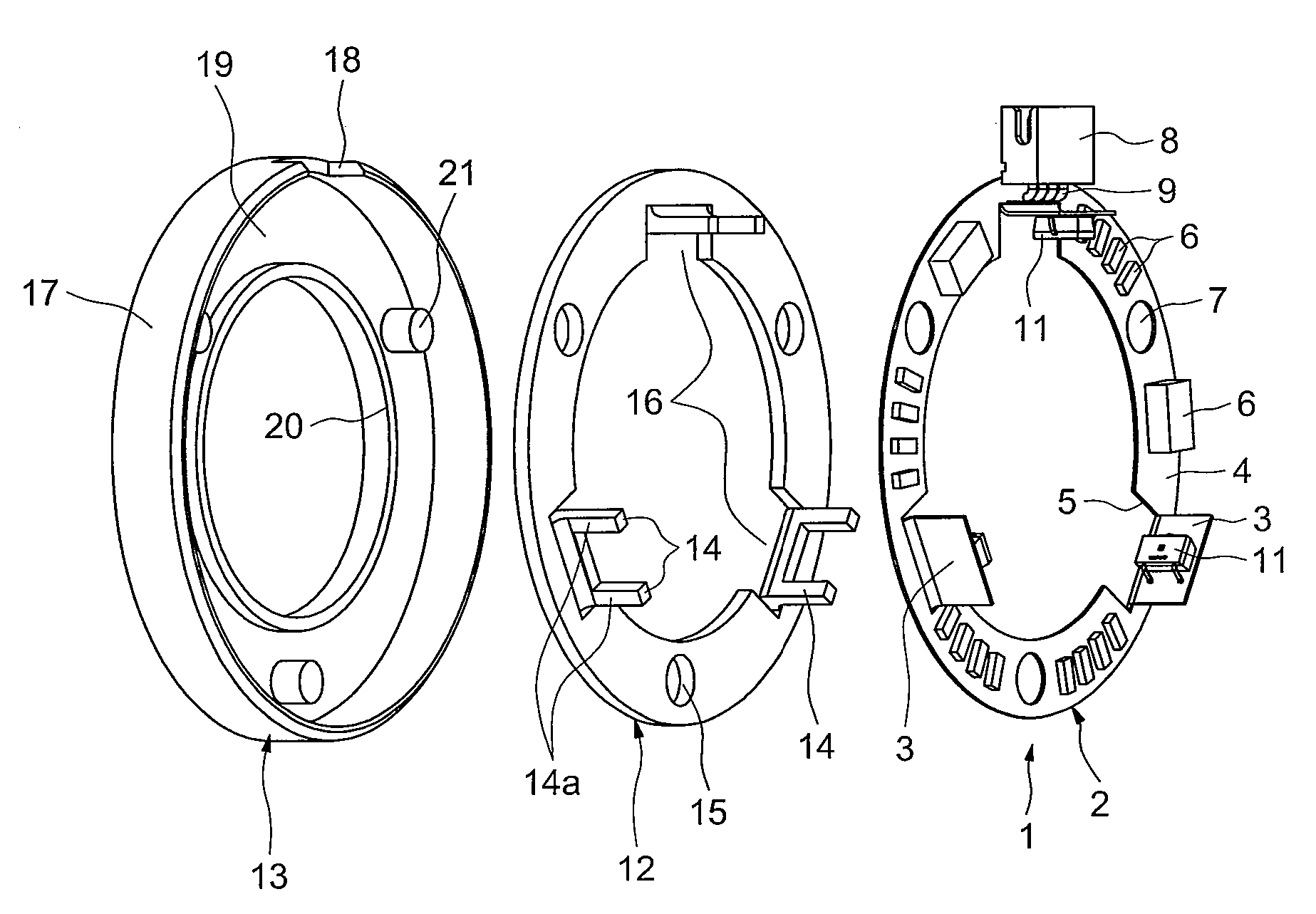
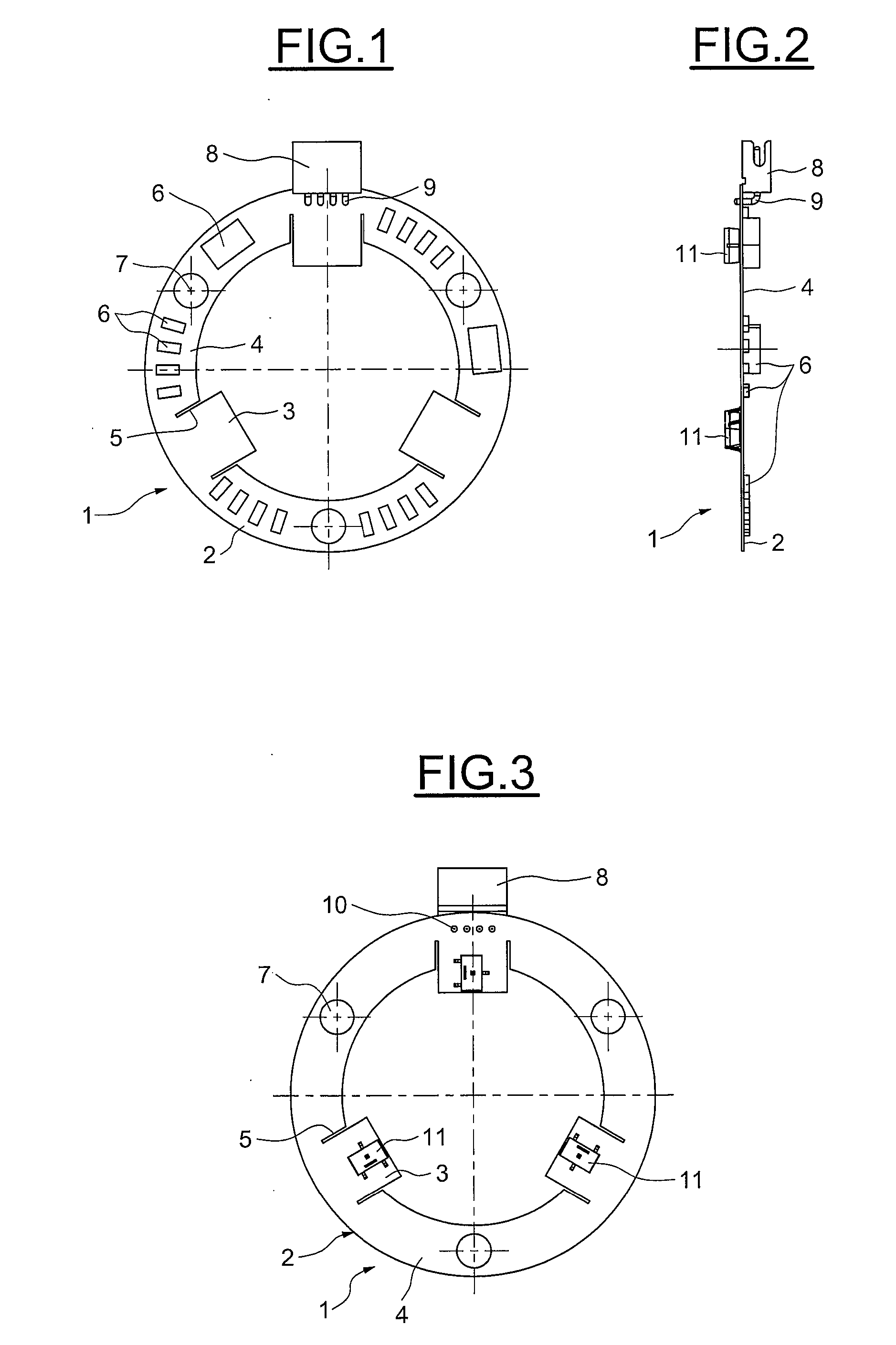
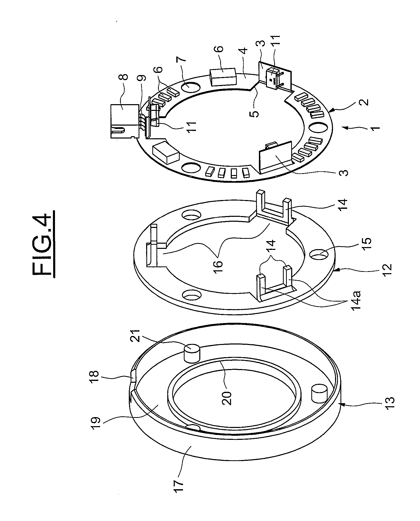
[0042]Generally in what follows, the reference numbers of similar elements have been retained from one figure to the next.

[0043]As illustrated in FIGS. 1 to 3, the electronic circuit board 1 includes a printed circuit 2 of the flexible and pliable type, for example including a polyamide-based substrate and one or more conducting layers. The printed circuit 2 has the general shape of an annular disc furnished with three tabs 3 extending radially towards the inside of the disc, cut-outs 4 being arranged between two sides of a tab 3 and the rest of the annular disc so that the rectangular-shaped tab 3 is connected only by one side to the annular disc 4, particularly the side opposite to the centre of the annular disc 4. The cut-outs 5 are preferably parallel with one another for each tab 3.

[0044]The printed circuit 2 supports electronic components 6 placed on the annular disc 4, for example by automated mounting with surface fixing. Three through-holes 7 are arranged in the annular dis...


PUM

PropertyMeasurementUnit
Mechanical propertiesaaaaaaaaaa

Abstract

Instrumented rolling bearing device for measuring the rotation parameters of the bearing, including a rotating race, a non-rotating race, at least one row of rolling elements placed between the non-rotating and rotating races, a rotating coder and a pliable non-rotating electronic circuit board comprising at least one sensor and at least one flat folded zone supporting the said sensor and pressing on a rigid reference surface forming part of a sensor block, at least one sensor being in the form of a spot-type detector cell.

Description

BACKGROUND OF THE INVENTION[0001]1. Field of the Invention[0002]The present invention relates to the field of instrumented rolling bearings furnished with a device for detecting the rotation parameters of the rolling bearing such as the angular position, the angular speed, or the angular acceleration of the rotating portion.[0003]2. Description of the Relevant Art[0004]Such rolling bearings usually use a coder ring fixed to the rotating portion, for example a multipolar ring and one or more sensors placed axially or radially opposite the active portion of the coder ring, for example Hall effect cells. The sensors are fixed to a rigid printed circuit board usually perpendicular to the axis of rotation of the rolling bearing. If a minimum axial space requirement of the rolling bearing is desired while obtaining a stable and repetitive output signal, it is possible to make use of the great radial rigidity of the rolling bearing and provide a radial air gap between the coder and the sen...

Claims


Application Information

Patent Timeline
IPC IPC(8): F16C32/00B21D53/10
CPCF16C19/54G01P1/00G01P1/026Y10T29/49636G01P3/487F16C41/007F16C33/723G01P3/443F16C19/06
Inventor DEBRAILLY, FRANCKSAUSSET, VINCENTABGRALL, LOIC
Owner AB SKF
Why Eureka
Try Eureka