
Shift fork and method for producing same

A fork-like and fork-leg technology is applied in the field of shift forks manufactured according to this method, which can solve problems such as unloaded optimization and achieve the effect of saving axial structural space

Inactive Publication Date: 2015-06-03
SCHAEFFLER TECH AG & CO KG
View PDF7 Cites 0 Cited by
  • Summary
  • Abstract
  • Description
  • Claims
  • Application Information

AI Technical Summary

Problems solved by technology

In addition, they require a relatively large amount of sliding material and are not load-optimized

Method used


Image

  • Shift fork and method for producing same
  • Shift fork and method for producing same
  • Shift fork and method for producing same

Examples


Embodiment Construction

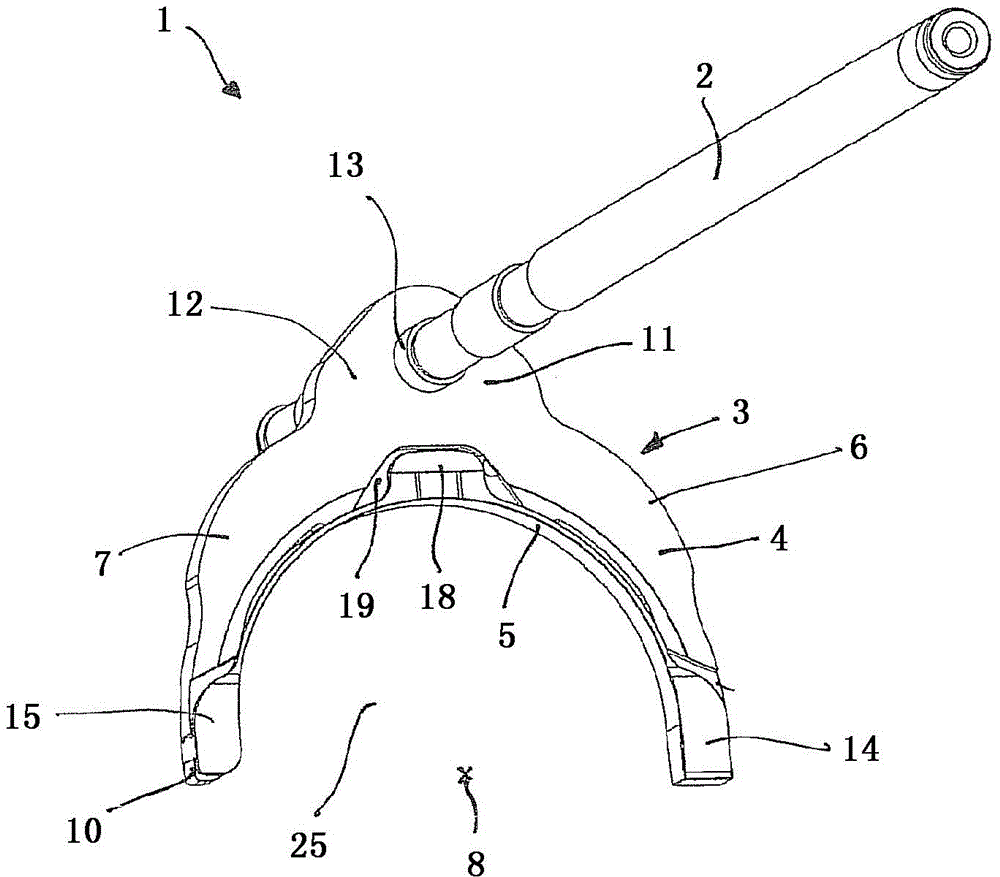
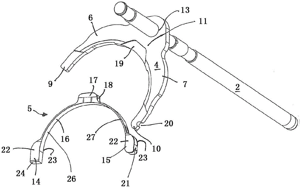
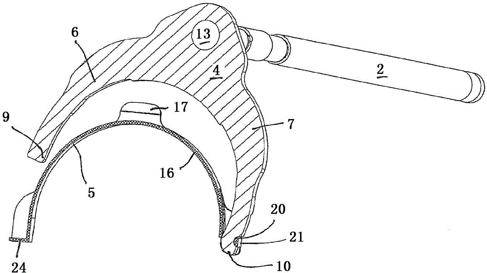
[0025] figure 1 Shown is a shifting unit 1 with at least a selector lever 2 and a shift fork 3 movable axially relative to a not-shown drive shaft. The shift fork 3 is firmly connected to the shift lever 2 so that movement of the shift lever 2 triggered by the operator or an actuator pushes the shift fork 3 axially for engaging or removing a gear by means of a shift bush not shown . The shift fork 3 has a body 4 and a sliding element 5 . The main body 4 is designed as an approximately semicircular stamped part made of sheet steel and has two fork legs 6 , 7 whose ends 9 , 10 are opposite relative to the drive axis 8 , that is to say offset from each other by approximately 180°. ground layout. The fork legs 6 , 7 narrow relatively towards their ends 9 , 10 as seen in cross section (relative to the transmission axis 8 ) and widen at the base 11 where the fork legs 6 , 7 are joined to each other in one piece . The connection of the selector lever 2 also takes place in the re...


PUM


Abstract

The invention relates to a shift fork (3) that has a fork-shaped main part (4) comprising fork limbs (6, 7) which lie opposite each other and which form a shift jaw (25) for guiding a shift collar. The shift fork also has a separately produced one-piece sliding element (5) for contacting the shift collar, said sliding element (5) having asymmetrical sliding limbs (26, 27) in the cross-sectional plane of the shift fork (3).

Description

technical field [0001] The invention relates to a shift fork with a fork-like body and a one-piece, separately produced slide element, wherein the fork-like body has mutually opposite fork legs, which form a shift jaw for guiding a shifting bushing , the sliding element is intended to be in contact with the gear bushing, and the invention also relates to a shift fork manufactured according to this method. Background technique [0002] A shift fork is known from the prior art, which has a shift jaw between two fork legs for engaging from the outside into a gear bushing. The gear sleeve is connected in a rotationally fixed manner to a synchronizing body arranged on the drive shaft, so that it rotates relative to a shift fork, which is stationary relative to the transmission housing. In order to avoid overloading the shift fork during the shifting process, these shift forks are usually provided end-to-end on their fork legs with separately produced sliding blocks. These slide...

Claims


Application Information

Patent Timeline
Patent Type & Authority Patents(China)
IPC IPC(8): F16H63/32
CPCF16H63/32F16H2063/324F16H2063/327
Inventor 乌韦·施瓦茨马蒂亚斯·费尔巴哈
Owner SCHAEFFLER TECH AG & CO KG
Learn More