Electric machine

一种定子、槽道的技术,应用在电力机车、机车、机动车等方向,能够解决增加所需空间、高压力降、灰尘积聚等问题,达到低重量水平、低产品成本的效果

Active Publication Date: 2020-09-04
BOMBARDIER TRANSPORTATION GMBH
View PDF10 Cites 0 Cited by
  • Summary
  • Abstract
  • Description
  • Claims
  • Application Information

AI Technical Summary

Problems solved by technology

However, this muffler adds to the cost of the motor and does take up considerable space, which is disadvantageous when the motor is used in a railway vehicle, since the space could otherwise be occupied by other equipment or used to make the motor more powerful. power
Another disadvantage of using mufflers manufactured from materials such as mineral wool is the accumulation of dust, which can lead to clogging of the outlet, resulting in higher pressure drop and thus less cooling of the motor
[0007] US5124600 discloses a motor with a muffler built into said structure forming the air outlet channel, but this muffler includes an expansion chamber and ducts, thereby greatly increasing the required space in the axial direction of the motor

Method used


Image

  • Electric machine
  • Electric machine
  • Electric machine

Examples


Embodiment Construction

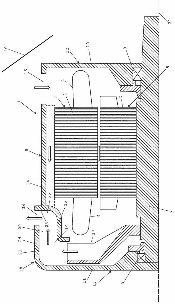
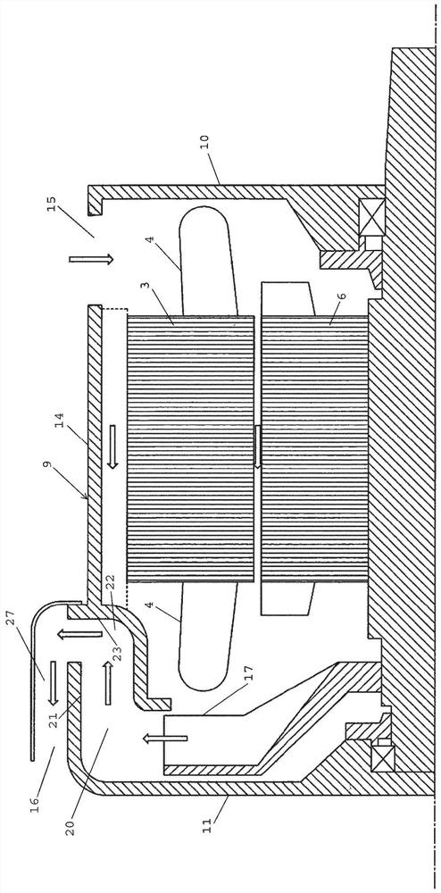
[0029] figure 1 An electric machine 1 according to a first embodiment of the invention is very schematically represented. It means that the motor is arranged in a rail vehicle 40, and the motor has a stator 2, the stator 2 has a stator body 3, the stator body 3 has a stator winding 4, and the stator winding 4 is arranged to generate electricity around the stator body A plurality of stator poles arranged around the inner periphery. The rotor 5 is arranged rotatably about a rotor axis 31 in the stator and has a rotor body 6 . The rotor may be provided with permanent magnets or any other type of components, such as conductive rings, for electromagnetic inductive interaction with the stator windings. The figure shows how the rotor is fixed on the rotor shaft 7 in the form of a rod received in a bearing 8 .

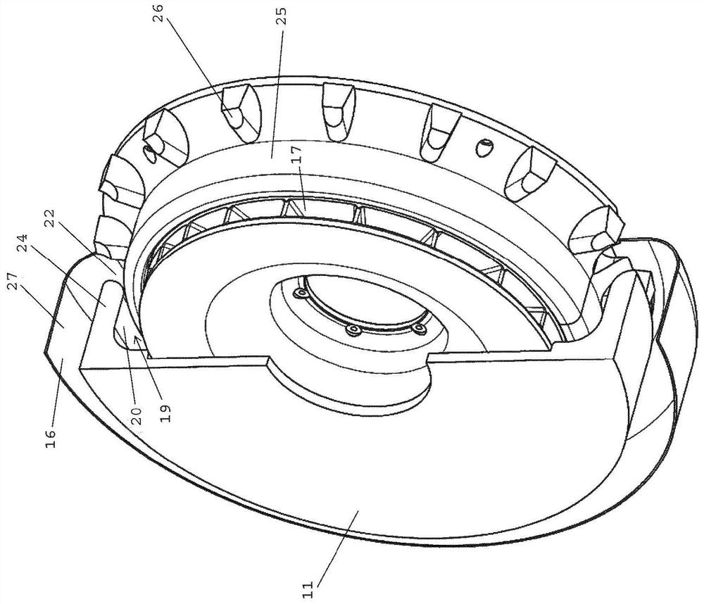
[0030] The electric machine has a housing 9 enclosing a rotor 5 and a stator body 3 with stator windings 4, and the casing comprises end shields 10, 11 arranged at respecti...


PUM


Abstract

The invention discloses an electric machine which comprises a housing (9) enclosing at least a rotor (5) and stator windings (4) of a stator (2) of the machine and comprising an end shield (10, 11) ateach axial end of the machine. The housing has an air inlet (15) at a first axial end (12) of the machine and a peripheral air outlet (16) at the other, second axial end (13) of the machine. A fan (17) is arranged in the housing at the second axial end to rotate with the rotor for creating a flow of air through the housing from the air inlet to the air outlet for cooling parts of the electric machine. An air outlet channel (19) conducts air radially leaving the fan to the air outlet (16). The channel has a first channel portion with first walls (21) directing air leaving the fan (17) axiallyback in the direction of the first axial end (12) and a second channel portion with second walls (23) redirecting the air flow from the fan to assume a major radial component.

Description

technical field [0001] The invention relates to an electrical machine comprising: a stator having a stator body having stator windings arranged to electrically generate a plurality of stator poles arranged around the inner periphery of the stator body; a rotor capable of Arranged rotatably within the stator and having a rotor body; a housing surrounding at least said rotor, stator body and stator windings and comprising end shields arranged at each axial end of the motor, said The housing has at least one air inlet at the first said axial end of the motor and at least one peripheral air outlet at the other second axial end of the motor; a fan fixed within the housing and positioned at at the second axial end so as to rotate with the rotor body so as to generate an air flow from the air inlet through the housing to the air outlet for cooling components of the motor; A structural member of an outlet channel configured to direct air radially exiting the fan to the air outlet. ...

Claims


Application Information

Patent Timeline
Patent Type & Authority Applications(China)
IPC IPC(8): H02K5/20H02K5/24H02K9/06
CPCH02K9/06H02K5/24H02K5/207B61C3/00H02K5/15
Inventor T·纳森E·博格曼P·阿斯普朗S·纳泰格J·林德贝格
Owner BOMBARDIER TRANSPORTATION GMBH
Why Eureka
Try Eureka