A launch vehicle and cutting assembly for separation between launch vehicle stages

A carrier rocket and inter-stage separation technology, applied to offensive equipment, projectiles, self-propelled bombs, etc., can solve problems such as increased labor intensity and complex structure of cutting components

Active Publication Date: 2021-04-13
北京星河动力航天科技股份有限公司 +2
View PDF8 Cites 0 Cited by
  • Summary
  • Abstract
  • Description
  • Claims
  • Application Information

AI Technical Summary

Problems solved by technology

The advantage of the technical solution disclosed in this patent document is that it can facilitate the installation of the pyrotechnic cutting cable protective cover, can reduce the requirement for the axial space of the cabin section, and can adjust the position of the pyrotechnic cutting cable protective cover in a large range, but The disadvantage is that since the detonator support is used as an independent component, and oblong holes need to be set on the protective cover of the pyrotechnic cutting cable and the detonator support, on the one hand, the structure of the cutting assembly becomes complicated; independent installation of the device support, increasing the labor intensity

Method used


Image

  • A launch vehicle and cutting assembly for separation between launch vehicle stages
  • A launch vehicle and cutting assembly for separation between launch vehicle stages
  • A launch vehicle and cutting assembly for separation between launch vehicle stages

Examples


Embodiment Construction

[0023] In order to make the technical problems, technical solutions and advantages to be solved by the present invention clearer, the following will describe in detail with reference to the drawings and specific embodiments.

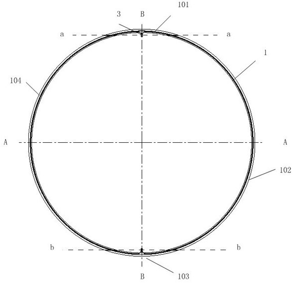
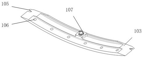
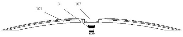
[0024] figure 1 The front view of the cutting assembly provided by the embodiment of the present invention; figure 2 and image 3 Schematic diagrams of the structure of the shroud ring segment with the detonator installed in the cutting assembly provided by the embodiment of the present invention; Figure 4 A cross-sectional view of the shroud ring segment with the detonator installed for the cutting assembly provided by the embodiment of the present invention; Figure 5 A schematic diagram of a cutting assembly provided with a reinforcing plate for an embodiment of the present invention.

[0025] Such as Figure 1 to Figure 4 As shown, the embodiment of the present invention provides a cutting assembly for interstage separation of a launch vehicle,...


PUM


Abstract

The invention provides a cutting assembly for separation between stages of a launch vehicle, comprising: a detonator, a pyrotechnic cutting cable and a pyrotechnic cutting cable protective cover; the pyrotechnic cutting cable protective cover includes Two long shield ring sections and two short shield ring sections are formed by cutting two planes in the direction, and the detonator mounting support and the detonation through hole are formed on the short shield ring sections; the pyrotechnic cutting cable includes rubber protection The sleeve and the drug strip, the rubber sheath is formed with a detonation groove, the detonation groove is arranged at a position corresponding to the detonation through hole, and the circumferential length of the detonation groove along the circumferential direction of the protective cover of the pyrotechnic cutting cable is greater than the diameter of the detonation through hole . The invention also provides a carrier rocket. The present invention can reduce the requirement on cabin space of the thermal cutting cable protective cover without increasing the structural complexity.

Description

technical field [0001] The invention relates to a cutting assembly for separation between stages of a launch vehicle, in particular to a cutting assembly capable of reducing the requirement for the axial space of a rocket cabin section when installing a thermal cutting cable protective cover. Background technique [0002] When the multi-stage launch vehicle is separated, it is necessary to use the pyrotechnic cutting cable to cut off the compartment to be separated, so as to realize the unlocking and separation of the compartment. In order to fix the pyrotechnic cutting cable to avoid flying out under the action of the impact force, and to prevent the blasting airflow and cabin fragments generated during the cutting process from injuring the equipment inside the cabin section, a pyrotechnic cutting cable will be installed on the inner wall of the cabin section. Cable protection cover. [0003] Patent document 1 (CN111453002A) discloses a launch vehicle, pyrotechnic cutting ...

Claims


Application Information

Patent Timeline
Patent Type & Authority Patents(China)
IPC IPC(8): F42B15/36F42B15/38
CPCF42B15/36F42B15/38
Inventor 刘百奇张沥刘建设
Owner 北京星河动力航天科技股份有限公司
Why Eureka
Try Eureka