Device and unit for the posterior dynamic guidance of the spine and treatment system comprising such a device

Active Publication Date: 2011-11-01
CLARIANCE SAS
View PDF7 Cites 8 Cited by
  • Summary
  • Abstract
  • Description
  • Claims
  • Application Information

AI Technical Summary

Benefits of technology

[0007]It is an object of the present invention to propose a device for the posterior dynamic guidance of the spine, that more faithfully reproduces the anatomical movement of the vertebrae by guiding these in a manner that is effective reliable and stable over time.
[0010]The idea underlying the invention is that of guiding the relative movements of the two vertebrae respectively equipped with the vertebral units, not by way of elastic elements connecting these units, but by way of the direct cooperation of these units, at their concentric spherical articulation surface(s) positioned on the posterior side of the vertebrae. In this way, the dynamic movement imposed on the vertebrae by the collaboration of these articulation surfaces is predetermined in a manner that is precise, reliable and stable over time. This dynamic movement can be likened to that of a pseudo-ball joint centered in the intervertebral space, preferably in the central region of this space, which causes the vertebrae to exhibit a dynamic articulation behavior similar to that of their normal anatomical behavior, both in terms of flexion-extension and in terms of twisting and lateral bending. Furthermore, collaboration between these articulation surfaces relieves the load on the disk that lies between the two vertebrae: the dimensions, particularly the vertical dimension, of the intervertebral space are actually maintained, in that this space is not reduced because the device according to the invention bears most, if not all, of the stresses associated with spinal movements. In other words, by virtue of the dynamic action of the device, the intervertebral disk is not compressed and therefore retains its normal anatomical mobility.
[0011]The invention also incorporates control over the amplitude of the relative movements of the vertebrae thus guided by the vertebral units, thanks to the dynamic limitation means. These means are effective and precise because of their mechanical nature. In addition, they have a two-fold practical effect: with respect to the vertebrae, they prevent these from departing from a preset range of freedom of movement, which is advantageously tailored to the build of the patient and / or to the condition being treated and, with respect to the vertebral units of the device, they are able to keep the articulation surfaces in contact with one another over substantial proportions of these surfaces, via which the mechanical stresses are effectively transferred between the vertebral units.
[0025]A further subject of the invention is a system for treating the spine, wherein the system comprises a device for posterior dynamic guidance of the spine as defined hereinabove and a means of temporarily immobilizing this device which is designed to be connected removably to the vertebral units and therefore prevent relative sliding of the articulation surfaces.
[0026]This immobilizing means makes the guide device easier to implant by temporarily neutralizing the internal mobility of this device, particularly while the vertebral units are being fixed to the vertebrae. The surgeon can then precisely determine the position at which to anchor the vertebral units, particularly in such a way as to locate the geometric center of the articulation surfaces appropriately, preferably in the central region of the intervertebral space. Once these vertebral units have been fixed to the vertebrae, the immobilizing means is disengaged by the surgeon and the intervention of implanting the device can be completed.

Problems solved by technology

This arthrodesis intervention does, however, lead to degeneration of the adjacent disks which then often require later treatment.
However, in practice, it proves tricky to use: it is difficult to determine the elasticity of the connecting elements because this elasticity has to be tailored to each patient according to his surgical requirement and build.
In addition, ultimately there is a risk that the elastic behavior of these elastic elements may change.
Imperfect control of the parameters relating to the elasticity of these elements means that the desired spinal mobility cannot be guaranteed and this may lead to mediocre guidance or even to instability in the intervertebral gap and aggravate the lesions that the intervention was supposed to be treating.

Method used


Image

  • Device and unit for the posterior dynamic guidance of the spine and treatment system comprising such a device
  • Device and unit for the posterior dynamic guidance of the spine and treatment system comprising such a device
  • Device and unit for the posterior dynamic guidance of the spine and treatment system comprising such a device

Examples


Embodiment Construction

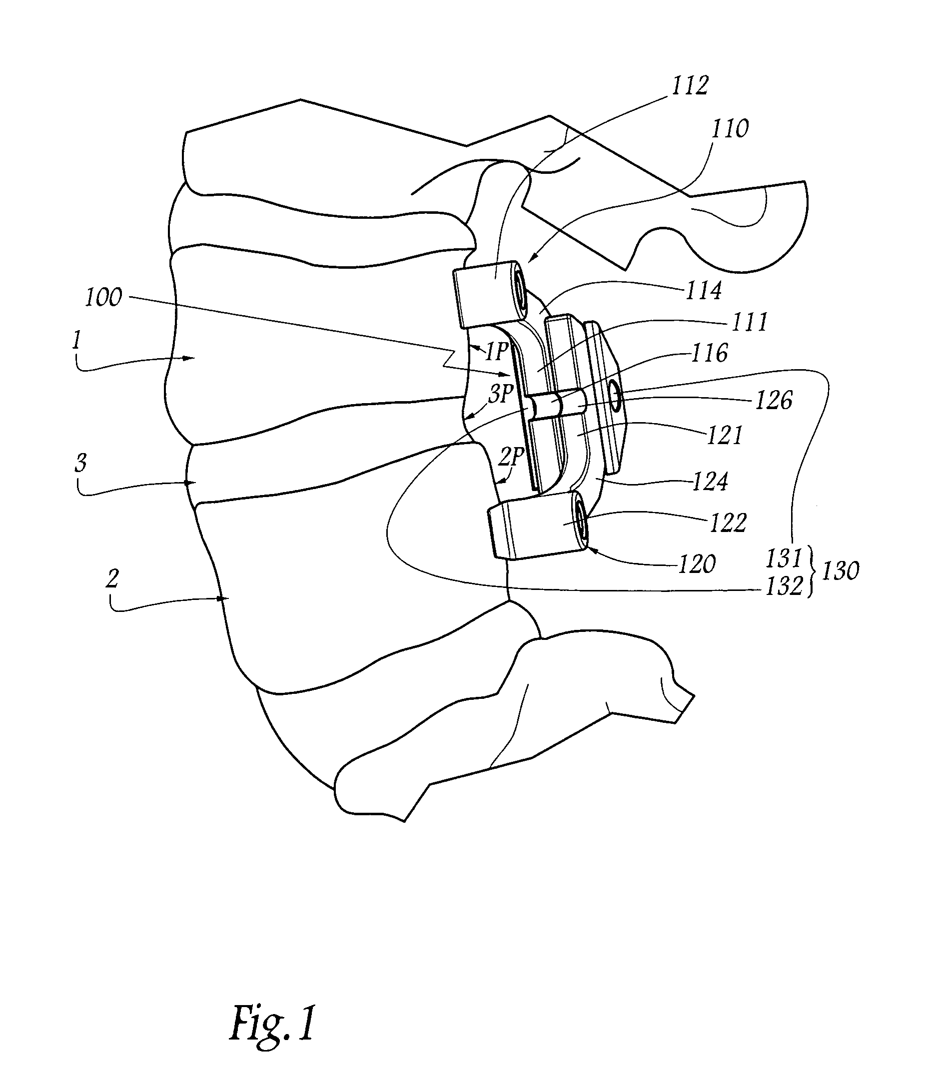
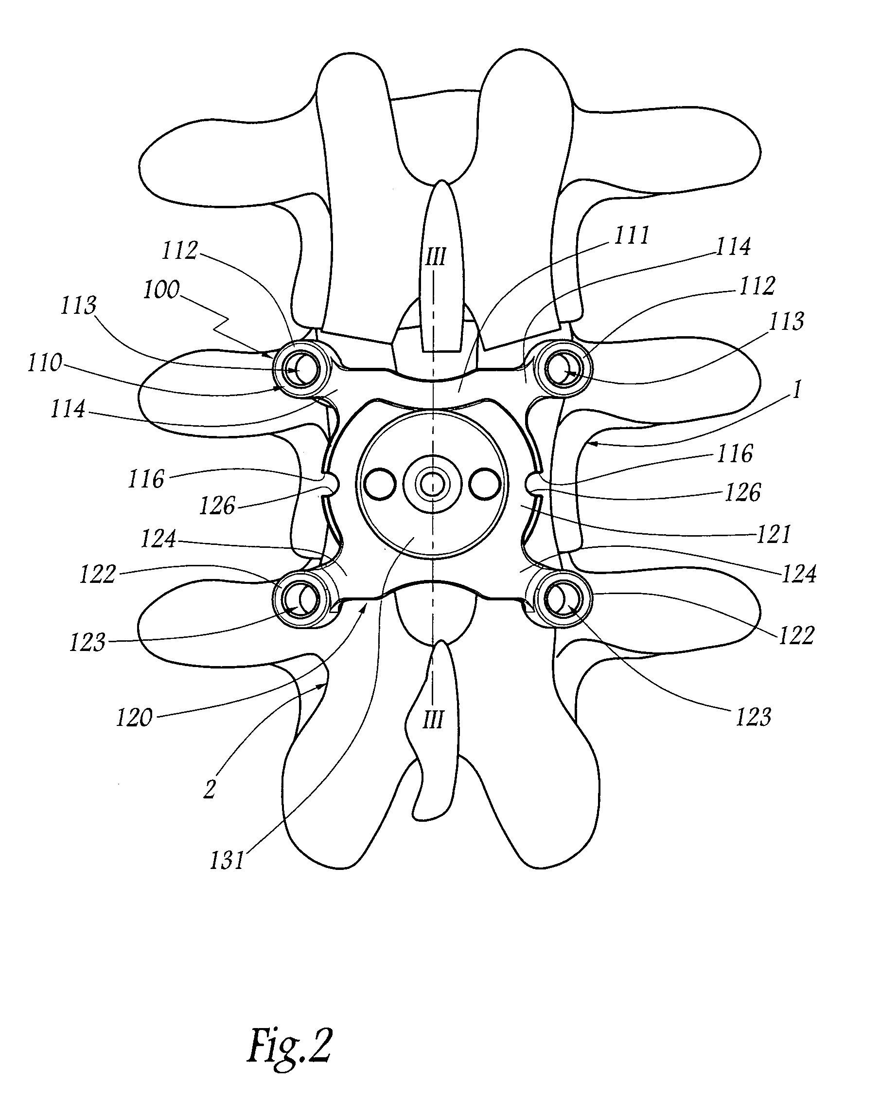
[0041]FIGS. 1 to 3 depict two adjacent vertebrae 1 and 2 of the lumbar spine of a human patient. These vertebrae are separated from one another by an intervertebral disk 3. For convenience, the remainder of the description is oriented with respect to these vertebrae in their anatomical position, that is to say that the terms “posterior” or “rear”, “anterior” or “front”, “right”, “left”, “superior”, “inferior”, etc. relate to the spine of the patient standing up.

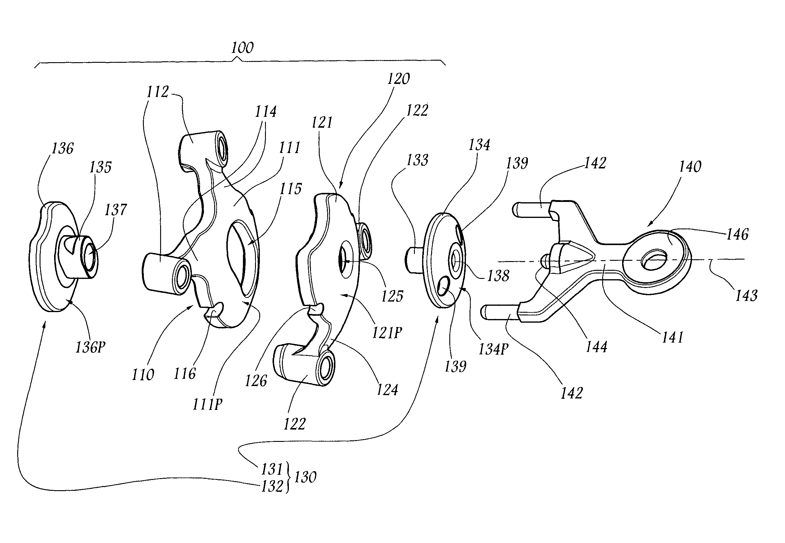
[0042]FIGS. 1 to 5 depict a device 100 for guiding the vertebrae 1 and 2, which is implanted on the posterior side of the vertebrae and is capable of providing a posterior articulated mechanical joint between these vertebrae, while at the same time maintaining the intervertebral space that vertically separates these vertebrae and which is occupied by the disk 3. The device 100 comprises a superior vertebral unit 110 implanted on the vertebra 1 and an inferior vertebral unit 120 implanted on the vertebra 2.

[0043]Each vertebral...


PUM


Abstract

A guidance device including two vertebral units adapted to be fixed to the posterior side of two adjacent vertebrae of the spine and wherein the two units have substantially spherical complementary articulation surfaces which, when the units are fixed to the vertebrae, extend overall on the posterior side of the vertebrae and slide against one another about a center point located in the intervertebral space that separates the vertebrae, and wherein the device also includes a mechanical element to limit an amplitude of the relative sliding of the articulation surfaces.

Description

BACKGROUND OF THE INVENTION[0001]1. Field of the Invention[0002]The present invention relates to a device for the posterior dynamic guidance of the spine, which is intended to be implanted along the posterior side of the spinal column in order to guide the movements of two adjacent vertebrae one relative to the other, by reproducing an intervertebral articulated joint. The invention also relates to a unit comprising at least two of these devices, and to a spinal treatment system comprising such a device.[0003]The invention thus relates to the treatment of degenerative spine disease or spinal trauma, particularly in the dorso-lumbar region of the spinal column, but also in the region of the cervical spine.[0004]2. Brief Description of the Related Art[0005]To treat intervertebral instability one known first option is to fuse two adjacent vertebrae, which amounts to depriving these two vertebrae of any freedom of relative movement. Completely rigid fixators are therefore implanted fixe...

Claims


Application Information

Patent Timeline
IPC IPC(8): A61B17/70
CPCA61B17/7059A61B17/808A61B17/8004
Inventor TORNIER, ALAIN
Owner CLARIANCE SAS
Why Eureka
Try Eureka