Measurement of EUV intensity

a lithographic system and radiation measurement technology, applied in the direction of optical radiation measurement, printers, instruments, etc., can solve the problems of reducing the throughput of lithography instruments, unable to place beam splitters b>103/b> in an euv lithography system, and unable to ensure beam properties

Active Publication Date: 2008-06-26
NIKON CORP
View PDF6 Cites 35 Cited by
  • Summary
  • Abstract
  • Description
  • Claims
  • Application Information

AI Technical Summary

Problems solved by technology

However, this procedure significantly reduces the throughput of the lithography instrument.
Further the beam properties would not be certain between measurements.
However, because EUV radiation is strongly absorbed by all materials, placing beam splitter 103 in an EUV lithography system is not possible.
However, this approach does no...

Method used


Image

  • Measurement of EUV intensity
  • Measurement of EUV intensity
  • Measurement of EUV intensity

Examples


Embodiment Construction

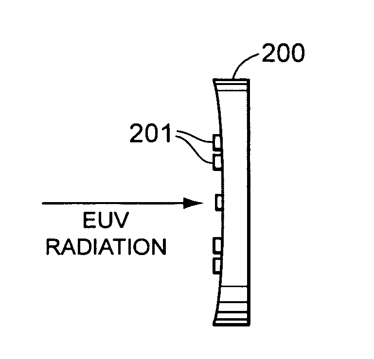
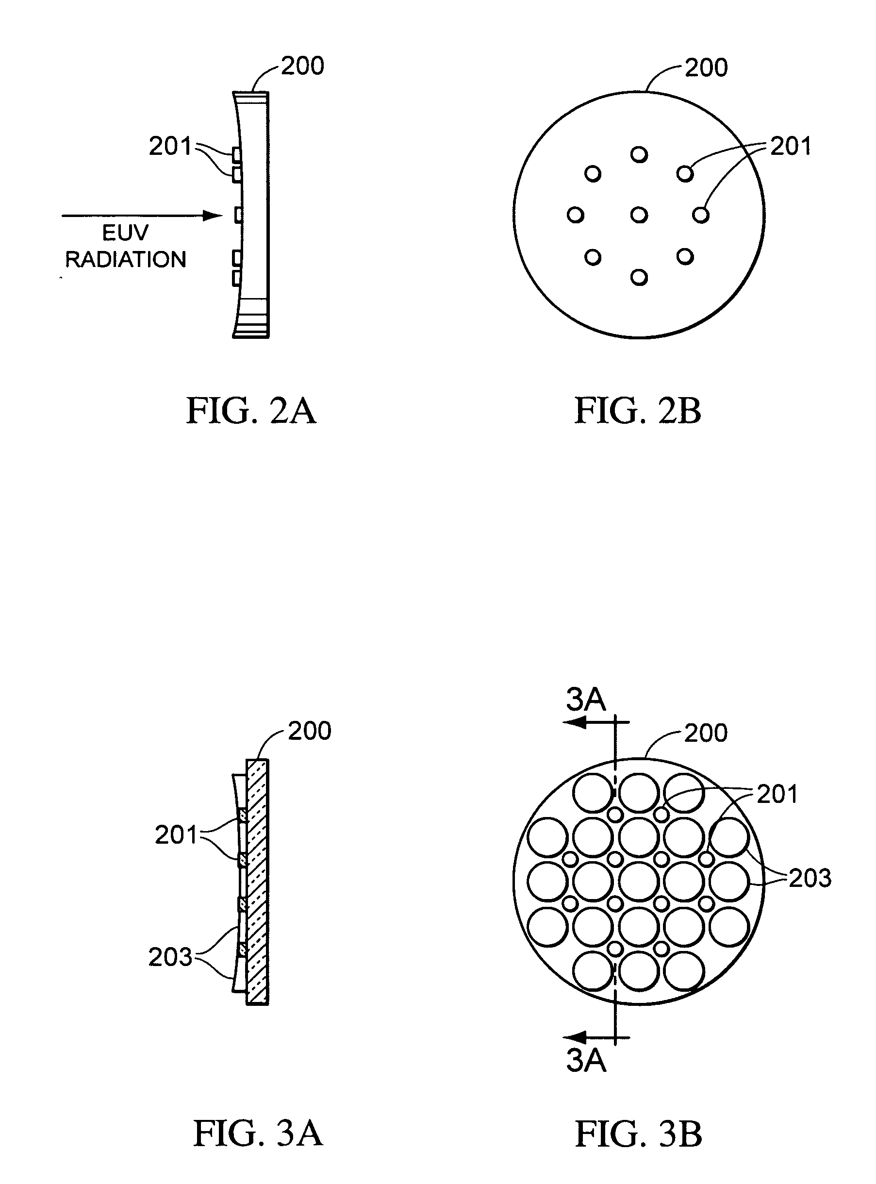
[0024]In an EUV lithography tool, the EUV intensity is accurately determined in order that the dose applied to the resist is controlled. Further, the intensity distribution is determined and controlled. In accordance with the present invention, the EUV intensity is measured at a plurality of positions on an EUV mirror positioned in the EUV beam of an EUV lithography system.

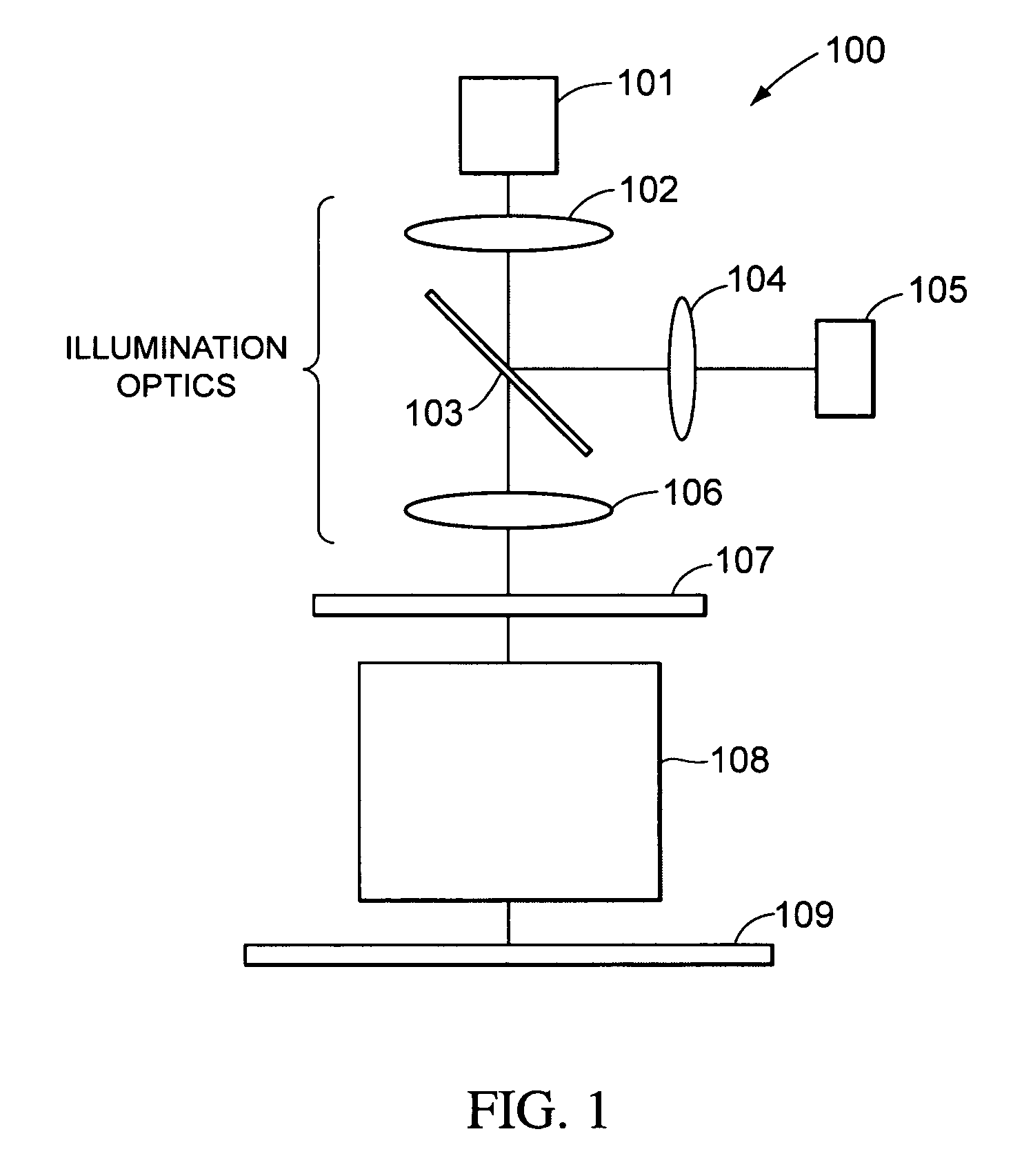
[0025]FIG. 9 illustrates an example of an EUV lithography system 900 according to some embodiments of the present invention. A radiation source 901 produces a beam of radiation that is collimated by mirrors 902 and 903 and focused onto a reticle 906 by mirrors 904 and 905. The reflected beam from reticle 906 is focused onto a substrate 909 by mirrors 907 and 908. Substrate 909 can be any substrate on which a lithographic process is being performed, including a semiconductor wafer on which semiconductor devices are being manufactured. In some embodiments, substrate 909 includes a photoresist layer that, after being...


PUM


Abstract

A monitoring system for an lithographic system is disclosed. In particular, the monitoring system can be utilized in an extreme ultraviolet lithographic system. In a monitoring system according to the present invention, a plurality of detectors are positioned to receive radiation from a pattern of positions on a mirror that is part of the lithographic system. In some embodiments, the plurality of detectors may be positioned on the mirror. In some embodiments, the plurality of detectors may be positioned behind the mirror and receive radiation through holes formed in the mirror. In some embodiments, radiation from the pattern of positions may be reflected by facets into the detectors.

Description

BACKGROUND[0001]1. Field of the Invention[0002]The present invention is related to the monitoring of radiation in a lithographic system and, in particular, to real time monitoring of radiation levels with minimal impact on radiation exposure within the lithographic system.[0003]2. Background of the Invention[0004]As the dimensions of semiconductor devices become smaller, so do the wavelengths of the radiation required in lithographic processes performed to deposit them. In order to efficiently print patterns of dimension 0.1 μm or less, lithography processes utilizing extreme ultra violet radiation (EUV) can be utilized. EUV utilizes light of wavelength about 10 to about 15 nm. The intensity and distribution of the EUV radiation applied to the resist should be controlled carefully in order to optimize the lithography process.[0005]Ideally, the intensity and intensity distribution is monitored in the wafer plane by moving a detector or detector array into the EUV beam at the location...

Claims


Application Information

Patent Timeline
IPC IPC(8): G01J3/00
CPCG01J1/04G01J1/0407G03F7/7085G01J1/429G03F7/70558G01J1/0455
Inventor SOGARD, MICHAEL
Owner NIKON CORP
Why Eureka
Try Eureka