
Screw-in Enossal Dental Implant

a screw-in enossal and dental implant technology, applied in dental implants, dental surgery, medical science, etc., can solve the problems of unfavorable distribution of compression forces on the jaw bone, and unsatisfactory shaving removal when the implant is screwed into the bone, so as to prevent infection caused by bacterial penetration, prevent gingival inflammation, and improve healing

Inactive Publication Date: 2008-06-19
BOETTCHER ROBERT
View PDF8 Cites 17 Cited by
  • Summary
  • Abstract
  • Description
  • Claims
  • Application Information

AI Technical Summary

Benefits of technology

[0011]7. has a groove arrangement in the crestal passage for preventing bone loss;
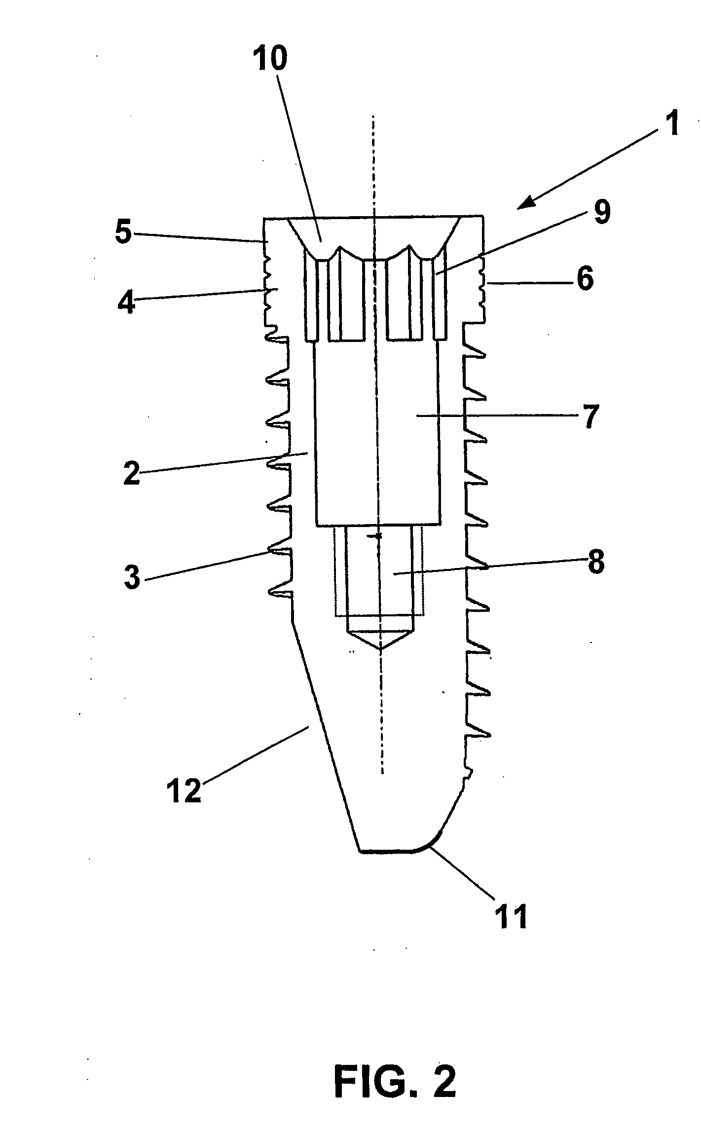
[0024]Moreover, embodied as the end on the upper part is a collar to which the conical part connects with preferably a hexagon socket and a bore with a thread. The conical part receives and the collar is a support for a cap that can be fixed with a fastening screw. The conical part is notched and offers anti-rotation protection for the cap to be received.

Problems solved by technology

Due to their geometric shape, the dental implants known from the prior art cause an unfavorable distribution of the compression forces on thejaw bone during the setting process.
In order to completely alleviate their effect in the upper area, the cervical portion of the implant is kept cylindrical, whereby closure problems and thus the risk of infection can arise because of the lack of just slight compression.
Furthermore, the notches are frequently dimensioned too small so that shaving removal when the implant is screwed into the bone is not satisfactory and there is no primary anti-rotational effect.
Frequently the thread flanks are also dimensioned too small and as a consequence the implant does not find an adequate hold in the bone.

Method used


Image

  • Screw-in Enossal Dental Implant
  • Screw-in Enossal Dental Implant
  • Screw-in Enossal Dental Implant

Examples


Embodiment Construction

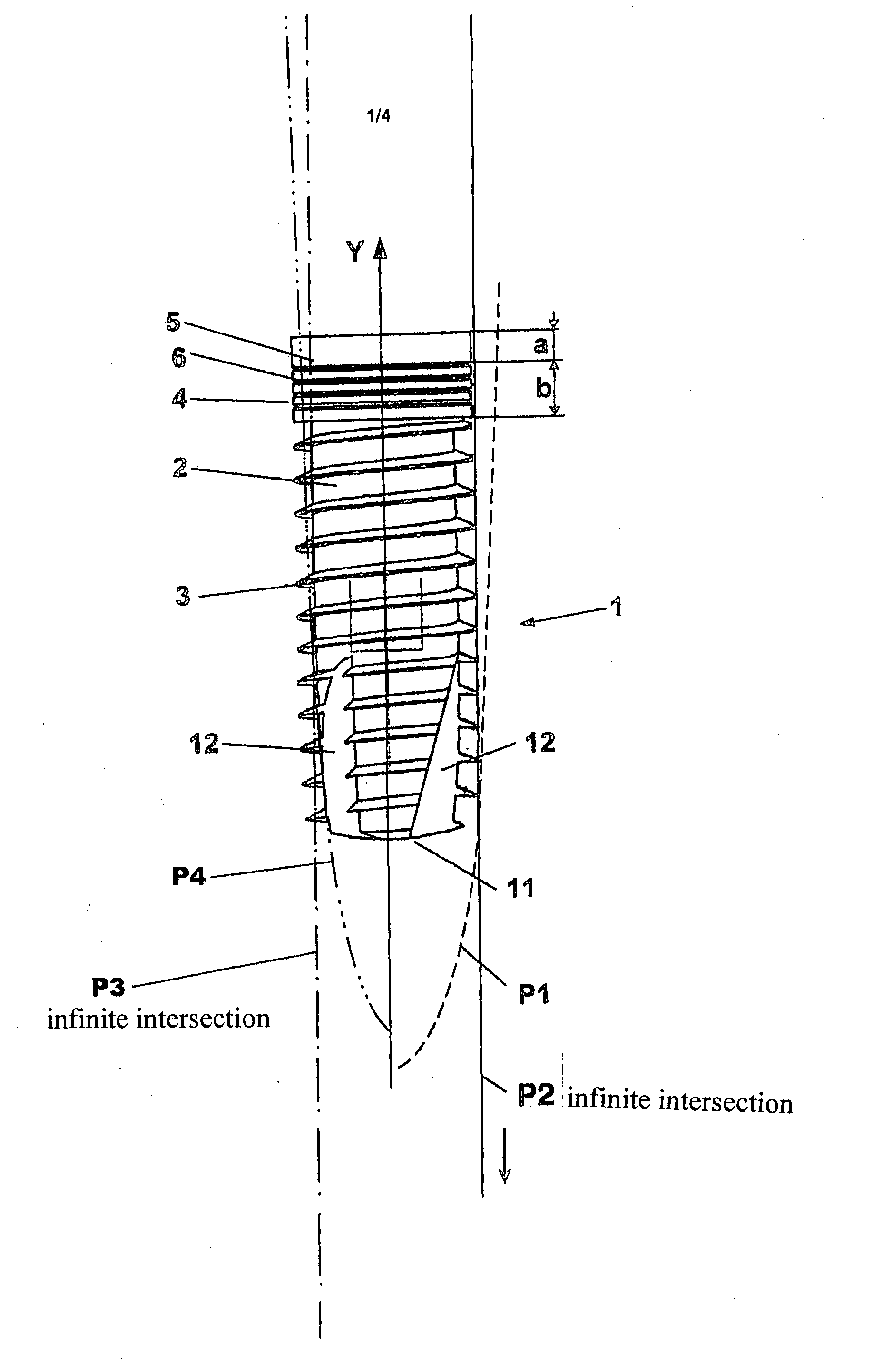
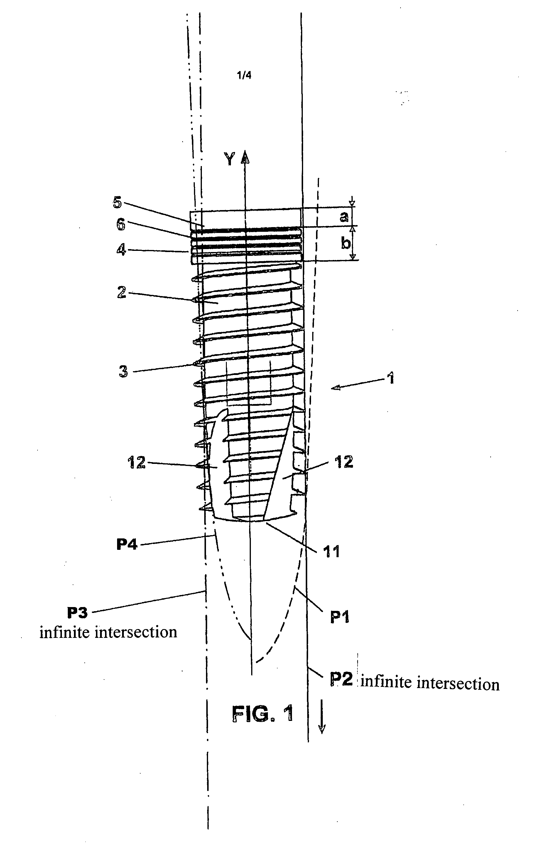
[0033]The inventive dental implant 1 in accordance with FIGS. 1 through 6 comprises a base body 2 that tapers from the crestal to the apical and that is provided from the apical to the crestal with a self-cutting asymmetrical thread 3, which can also be multi-threaded, having a largely constant or imperceptibly decreasing thread depth. The thread cross-section forms a scalene triangle, the flank angle of which is 20 degrees. The thread height and thus the thread 3 are enclosed in parabolas P1, P2 and P3, P4, whose axis of symmetry is that of the base body 2 and to make this easier to visualize is the Y axis of a Cartesian coordinate system. The advantageous selection of the parabolas P3 and P4 determines the thread arrangement on the base body 2, the parabolas P1 and P2 limiting the thread tip. The parabolas P1 and P2 intersect outside of the area of the dental implant 1, as shown in FIG. 1. Thus the thread arrangement runs from the apical to the crestal. The thread 3 reaches a thre...


PUM


Abstract

A screw-in enossal dental implant comprising a base body with a thread arrangement which can be multiple-threaded, and notches, in addition to an upper part and a bulged enossal part. The thread arrangement on the base body is defined by parabolic curves forming intersection points outside the area of the dental implant. The thread arrangement extends as far as the upper part. The flank angle of the thread flanks is 20 DEG. The transition between the base body and the bulged enossal part is rounded. The maximum depth of the notches is ⅓ of the diameter of the base body and the width thereof is at least as large as the width of the respectively remaining thread arrangement between the notches. The dental implant causes the compression forces acting upon the jaw bone to tend unevenly towards zero as the screw-in depth increases, enabling reliable fastening in the enossal area.

Description

BACKGROUND OF THE INVENTION[0001]The invention relates to a screw-in enossal dental implant having a parabolic base body that has a self-cutting thread arrangement that is provided with at least two notches and that can also be multi-threaded and that has a parabolic thread base, and having an upper part provided coronal to the thread arrangement with a shaped hole to assist with screwing in and a thread for attaching and fixing tooth crowns, bridges, and the like, and having a bulged enossal part and where necessary a cone part and / or a cap.[0002]Screw-in dental implants, including those with a self-cutting thread, have been known for a long time in a variety of embodiments.[0003]Thus for instance known from patent DE 3735378 C2 is a dental implant having an anchoring apparatus that comprises a longitudinally extended cylindrical base body, the thread of which runs slightly conically in the lower part. In this case an opening that runs outward is provided into which bone tissue can...

Claims


Application Information

Patent Timeline
IPC IPC(8): A61C8/00
CPCA61C8/0025A61C8/0022
Inventor BOETTCHER, ROBERT
Owner BOETTCHER ROBERT
Learn More