
Multi-layer rotationally molded low permeation vessels and method for manufacture thereof

Active Publication Date: 2008-06-19
CENTRAL
View PDF24 Cites 17 Cited by
  • Summary
  • Abstract
  • Description
  • Claims
  • Application Information

AI Technical Summary

Benefits of technology

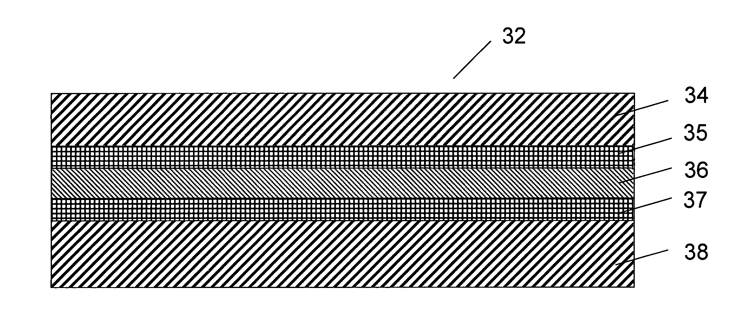
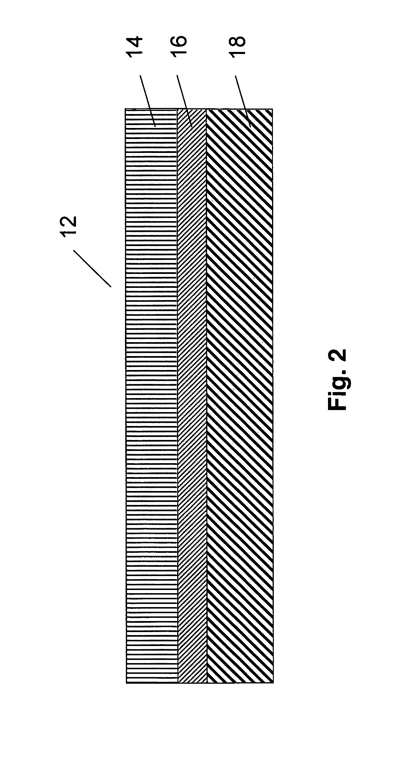
[0009]According to the invention, the vessel comprises the use of successive layers of materials to produce a multi-layer structure, with low permeation properties. Two of these layers, which form the external and internal layers of the vessel, are between 0.1 mm and 20 mm thick and are made from crosslinked polyethylene (a thermoset material), with a density of between 0.92 and 0.96 g / cm3. Another layer is located between the thermoset layers, and is between 0.1 mm and 10 mm thick and is made from ethylene-vinyl alcohol copolymer, with a density of between 1.00 and 1.30 g / cm3. This type of multi-layer structure is of particular benefit when functioning as a fuel tank or vessel to minimize the transfer of vapors or emission of the fluid or gas being contained at low pressure.
[0012]Depending on the choice of materials and the processes implemented, a multi-layer vessel can have layers composed of different materials. However, what is required is an impermeable thermoplastic core surrounded by a thermoset material on each side. It is the primary object of the invention to provide a low cost, low permeation vessel of high impact resistance.

Problems solved by technology

Also, the rotational molding process allows very complex shapes to be manufactured from these types of materials.
However, crosslinked polyethylene does allow the permeation of hydrocarbons and other fluids and vapors at rates that do not conform to some current and future environmental regulations e.g. California Air Resource Board (CARB) and the Environmental Protection Agency (EPA).
However, Polyamide 11 lacks low temperature dart impact strength, which may limit the applications it can be used for.
The cost of Polyamide 11 may also be a limiting factor.

Method used


Image

  • Multi-layer rotationally molded low permeation vessels and method for manufacture thereof
  • Multi-layer rotationally molded low permeation vessels and method for manufacture thereof
  • Multi-layer rotationally molded low permeation vessels and method for manufacture thereof

Examples


example 1

[0067]A vessel composed of a 1.5 mm thick layer of crosslinked polyethylene on the outside, a 1 mm thick layer of ethylene-vinyl alcohol copolymer in the middle and a 2.5 mm thick layer of crosslinked polyethylene on the inside, was manufactured using the rotomolding process. The vessel was manufactured using commercial grades of these materials, with melting temperatures of approximately 125° C. for crosslinked polyethylene and 160° C. for ethylene-vinyl alcohol copolymer.

[0068]The molding cycle consisted of charging the mold with enough crosslinkable polyethylene material so as to form the 1.5 mm (average) thickness external layer. Once this material had melted and fused together, the second layer of ethylene vinyl alcohol copolymer was added to the mold through the vent port forming a 1 mm thick middle layer. Once the middle layer had melted and fused together, a third layer of crosslinkable polyethylene was added to the mold through the vent port forming the 2.5 mm inner layer o...

example 2

[0076]A vessel composed of a 2 mm thick layer of crosslinked polyethylene mixed with ethylene-vinyl alcohol copolymer on the outside, a 0.5 mm thick layer of ethylene vinyl alcohol copolymer in the middle and a 2.5 mm thick layer of crosslinked polyethylene on the inside, was manufactured using the rotomolding process. The vessel was manufactured using commercial grades of these materials, with melting temperatures of approximately 125° C. for crosslinked polyethylene and 160° C. for ethylene-vinyl alcohol copolymer.

[0077]The molding cycle consisted of charging the mold with both crosslinkable polyethylene and ethylene-vinyl alcohol copolymer. Once these two materials had melted and separated to form the first two layers, a charge of crosslinkable polyethylene was added to the mold using a dropbox forming the 3 mm inner layer of the vessel. During this process, the internal air temperature of the molding cycle was monitored and used to determine when each layer had formed and theref...

example 3

[0082]A vessel composed of a 1.5 mm thick layer of crosslinked polyethylene on the outside, a 0.5 mm thick layer of maleic anhydride grafted polyethylene, a 1 mm thick layer of ethylene-vinyl alcohol copolymer, a 0.5 mm thick layer of maleic anhydride grafted polyethylene, and a 2.5 mm thick layer of crosslinked polyethylene on the inside, was manufactured using the rotomolding process. The vessel was manufactured using commercial grades of these materials.

[0083]The molding cycle consisted of charging the mold with enough crosslinkable polyethylene material so as to form the 1.5 mm (average) thickness external layer. Once this material had melted and fused together, maleic anhydride grafted polyethylene was added to the mold through the vent port. Once the maleic anhydride layer had melted and fused together into a layer, a charge of ethylene vinyl alcohol copolymer was added to the mold through the vent port. Once the EVOH layer had melted and fused together, a second charge of mal...


PUM

PropertyMeasurementUnit
Temperatureaaaaaaaaaa
Lengthaaaaaaaaaa
Lengthaaaaaaaaaa

Abstract

A multiple walled enclosure with low permeation properties and rugged impact resistance useful as a fuel tank or chemical container. The enclosure is made by rotomolding a first charge of thermosetting polymer into an outer layer, then rotomolding a charge of EVOH or other low permeation thermoplastic into a second layer, then rotomolding a second charge of thermosetting polymer into a third layer so that the low permeation thermoplastic layer is fully enclosed by layers of thermoset polymer. The preferred thermosetting polymer is crosslinkable polyethylene and the preferred low permeation thermoplastic is EVOH.

Description

CROSS-REFERENCE TO RELATED APPLICATIONS[0001]This application claims priority from co-pending provisional patent application entitled “Multi-Layer Rotationally Molded Low Permeation Vessel And Method for Manufacture Thereof,” Ser. No. 60 / 875,196 filed Dec. 15, 2006. The disclosure of provisional patent application Ser. No. 60 / 875,196 is hereby incorporated in its entirety.FIELD OF INVENTION[0002]This invention relates to a process for manufacturing hollow seamless plastic parts using the rotational molding process.BACKGROUND OF THE INVENTION[0003]For current rotomolding fuel tank technology, single layer (typically 2.5 to 20 mm thick) crosslinked polyethylene is commonly used for the production of fuel tanks, chemical vessels and many other containment-type products. This material is widely known as having very tough and durable qualities that allow it to be used in such demanding applications. Also, the rotational molding process allows very complex shapes to be manufactured from t...

Claims


Application Information

Patent Timeline
IPC IPC(8): B32B1/08B32B27/08B29C45/14
CPCB29C41/003B29C41/06B29C41/22B29K2995/0069Y10T428/1352B32B27/08B32B1/02B65D25/00Y10T428/1379B29L2031/7172B32B1/00
Inventor SPENCE, ALVIN G.KNEPPER, JEREMY R.GRIMES, DANIEL D.
Owner CENTRAL
Learn More