
Fluidized Bed System for Single Step Reforming for the Production of Hydrogen

Inactive Publication Date: 2008-06-19
TEXACO INC
View PDF4 Cites 30 Cited by
  • Summary
  • Abstract
  • Description
  • Claims
  • Application Information

AI Technical Summary

Benefits of technology

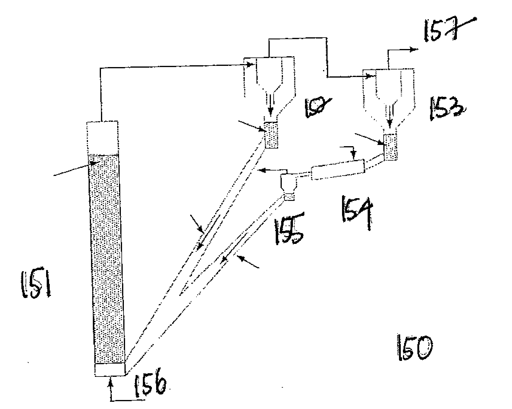
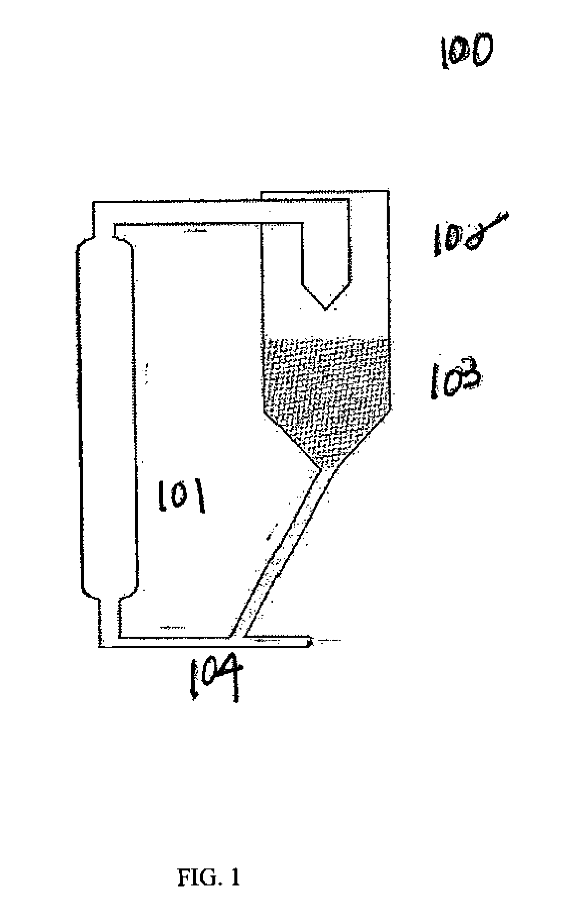
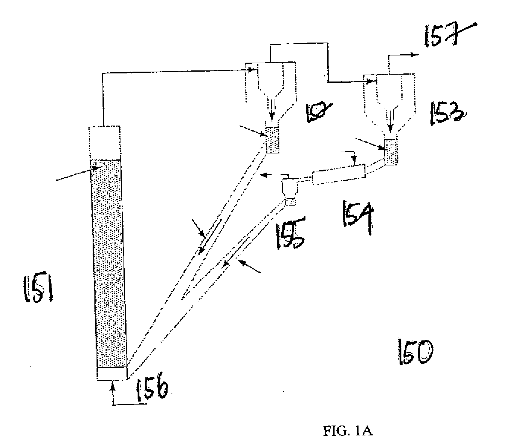
[0009]In the present invention, to address the heat transfer and the replenishment issues associated with single step reforming (SSR), the sorbent particles are mobilized. In the present invention, the technique to achieve this result is to fluidize the sorbent particles. This fluidization allows the sorbent particles to be regenerated and consequently allows the optimal operating conditions for SSR to be maintained.

Problems solved by technology

While there is wide-spread consumption of hydrogen and great potential for even more, a disadvantage which inhibits further increases in hydrogen consumption is the absence of a hydrogen infrastructure to provide widespread generation, storage and distribution.
However, in addition to the desired hydrogen product, fuel reformers typically produce undesirable impurities that reduce the value of the reformate product.
While such purification technologies may be known, the added cost and complexity of integrating them with a fuel reformer to produce sufficiently pure hydrogen reformate can render their construction and operation impractical.
Moreover, the catalysts employed in many types of fuel cells can be deactivated or permanently impaired by exposure to certain impurities that are commonly found in conventionally reformed fuels.
However, the reaction of CaO with CO2 is a gas to solid reaction whereby the sorbent CaO particles are continuously depleted in the typical plug flow fixed bed reactor.
This process involves heating the sorbent in place by flowing superheated steam and / or exhaust combustion gas at a temperature above 750° C. This cyclical thermal re-processing and semi-batch operation may yield a sub-optimal net thermal energy efficiency of the overall system, may require a larger reactor system, may complicate operations, and may cause thermal degradation of the sorbent particles which cannot be easily accessed for replenishment.

Method used


Image

  • Fluidized Bed System for Single Step Reforming for the Production of Hydrogen
  • Fluidized Bed System for Single Step Reforming for the Production of Hydrogen
  • Fluidized Bed System for Single Step Reforming for the Production of Hydrogen

Examples


Embodiment Construction

[0027]Illustrative embodiments of the invention are described below. In the interest of clarity, not all features of an actual embodiment are described in this specification. It will of course be appreciated that in the development of any such actual embodiment, numerous implementation-specific decisions must be made to achieve the developers' specific goals, such as compliance with system-related and business-related constraints, which will vary from one implementation to another. Moreover it will be appreciated that such a development effort might be complex and time-consuming, but would nevertheless be a routine undertaking for those of ordinary skill in the art having the benefit of this disclosure.

[0028]The instant invention is generally directed to reactors, apparatuses and methods for converting a hydrocarbon-based fuel to a hydrogen-rich reformate. The invention simplifies the production of a highly pure hydrogen-rich reformate by incorporating a carbon dioxide fixing mechan...


PUM


Abstract

The present invention discloses a fluidized bed system for the single step reforming technology for the production of hydrogen. Single step reforming combines the steam methane reforming, water gas shift, and carbon dioxide removal in a single step process of hydrogen generation. In the present invention, to address the heat transfer and the replenishment issues associated with single step reforming, the sorbent particles are fluidized. This fluidization allows the sorbent particles to be regenerated and consequently allows the optimal operating conditions for single step reforming to be maintained.

Description

FIELD OF THE INVENTION[0001]The present invention relates generally to a reactor system for the production of hydrogen. The present invention relates specifically to a fluidized bed system for single step reforming for the production of hydrogen.BACKGROUND OF THE INVENTION[0002]Hydrogen is utilized in a wide variety of industries ranging from aerospace to food production to oil and gas production and refining. Hydrogen is used in these industries as a propellant, an atmosphere, a carrier gas, a diluent gas, a fuel component for combustion reactions, a fuel for fuel cells, as well as a reducing agent in numerous chemical reactions and processes. In addition, hydrogen is being considered as an alternative fuel for power generation because it is renewable, abundant, efficient, and unlike other alternatives, produces zero emissions. While there is wide-spread consumption of hydrogen and great potential for even more, a disadvantage which inhibits further increases in hydrogen consumptio...

Claims


Application Information

Patent Timeline
IPC IPC(8): F27B15/00
CPCB01J8/0055F27B15/00B01J8/1863B01J2208/00292B01J2208/00752B01J2208/00761C01B3/44C01B2203/0233C01B2203/0244C01B2203/0283C01B2203/0425C01B2203/0475C01B2203/1052C01B2203/1064C01B2203/107C01B2203/1094C01B2203/1241C01B2203/1247C01B2203/1276C01B2203/148C01B2203/86C01F11/18B01J8/1809Y02P10/122Y02P10/143Y02P30/00
Inventor BAVARIAN, FARSHADSTEVENS, JAMES F.KRISHNAMURTY, BALAJILIU, YUNQUANKRAUSE, CURTIS L.YOU, LIXINCASEY, DANIEL G.
Owner TEXACO INC
Learn More