Reduced threads coaxial connector

Inactive Publication Date: 2008-06-12
HO KESSE C
View PDF1 Cites 29 Cited by
  • Summary
  • Abstract
  • Description
  • Claims
  • Application Information

AI Technical Summary

Benefits of technology

[0026]According to the invention, the inner helically threaded wall surface of the male tubular connector body is adapted to threadingly engage the threaded outer cylindrical wall surface of the outer conductive tubular shell portion of a conventional complementary female coaxial connector which the reduced thread male coaxial connector is adapted to mate with. This construction allows the threaded female connector shell to be inserted a substantial distance into the smooth bore portion of the male connector body bore before contacting the threaded portion of the male connector body bore. The smooth bore thus serves as a tubular pilot guide which ensures that male and female connectors are axially aligned before inner and outer respective threaded surfaces thereof make contact. Thus, axial misalignment of the male and female coaxial connectors is precluded, facilitating threadingly tightening the connectors together. Moreover, the reduced number of threads in the male connector, e.g., 1 to 3 rather than 5 to 8, reduces proportionately the number of turns required to tighten or loosen a connection made by the connector.
[0028]A male reduced threads coaxial connector according to the present invention preferably has a construction which facilitates making an electrically conductive connection between the outer conductive tubular body of the connector and the outer conductor of a coaxial line, such as an outer braided metal sheath of a coaxial cable. That construction may consist of a rear crimp ring, a solderable or weldable rear body surface, or any other suitable expedient.
[0029]Also, a male reduced threads coaxial connector according to the present invention preferably has a construction which facilitates making electrical contact between a central axial conductor of a female coaxial connector and a center conductor of a coaxial line which the male coaxial connector terminates. That construction may consist of a central coaxial aperture through the male tubular connector body, which is adapted to receive axially therethrough the center conductor of a coaxial cable that protrudes longitudinally forwards sufficiently far to be received in a conductive central ferrule of a female coaxial connector threadingly engaged with the reduced threads male coaxial connector.
[0030]A female embodiment of a reduced threads coaxial connector according to the present invention has a construction similar to that of prior art female coaxial connectors of the type having an elongated cylindrically-shaped outer conductive shell which is provided with an external helically threaded surface that extends from an outer transverse end wall of the shell over a substantial portion of the length of the shell. However, the outer cylindrical wall surface of the shell of a reduced threads female coaxial connector according to the present invention has a smooth, unthreaded surface of a diameter less than that of the threaded portion of the shell. The unthreaded surface extends an appreciable axial distance inwardly of the outer transverse end wall of the shell, e.g., more than 25 percent. This construction affords the advantages of pre-alignment and reduced number of turns required for connecting and disconnecting the female coaxial connector from a male coaxial connector, for the same reasons as described above for the male reduced thread coaxial connector.

Problems solved by technology

Although push-on connectors of the type described above are sometimes used in indoor applications, such use is generally confined to low frequency video applications, because of their poor RF characteristics as compared to threaded connectors.
Moreover, they are unsuitable for outdoor use because typical push-on connectors are not water-tight, and therefore may admit dust as well as atmospheric moisture in the form of rain or condensation into the interior of the connector pair.
Such moisture is problematic not only because it can corrode and degrade connector components, but because it can substantially alter both DC and RF electrical properties of the connector pair.
Thus, as is well known to those skilled in the art, connecting a coaxial cable of a particular characteristic impedance to a mismatched impedance caused by variations in electrical properties of a connector will result in significant signal insertion loss and reflections.
One of the problems with fully-threaded connectors is that when they are deployed in the field for a period, and exposed to weather conditions, the connectors often become dirty, corroded and difficult to unscrew without the use of a wrench.
Corrosion occurs because the rubber O-ring at the bottom of the male connector may stop water and moisture from reaching the inner conductors, but water and dirt can still penetrate voids between mating connector threads.
Therefore, the more threads there are on a nnector, the harder it may become to unscrew the connector afer exposure to the elements.
Furthermore, conventional screw-on, screw-off operations become laborious when the number of connections to be made is increased.
As a result, an installer may fail to screw a connector in all the way, thus again resulting in moisture entering the connector even if there is a rubber O-ring seal at the base of the male-connector.
Moisture in a connection changes the system characteristic impedance and causes RF signal reflection, a very undesirable condition in any video or RF frequency application, which can be characterized as a degradation in Return Loss (RL).
A mis-match causes degradation of signal power transfer and degradation of system frequency response.
But weather boots are bulky and of limited use in tight spaces.
Also, changes in temperature during the days and the nights can cause moisture to be admitted into the connection.
Another problem with fully-threaded connectors is initial alignment.
The connectors will not mate if they are not perfectly aligned, necessitating trial-and-error time to be expended by an installation technician.
Mis-alignment can result in cross-threading, and may damage the male and / or female threads if forced, thus making removal even more difficult.
Since cross-threading often results in imperfect mating, the potential of allowing water and / or moisture to accumulate in the connector cavity is increased, even if the intended rubber “O” ring is in place.
But connections made by push-on connectors are not water / moisture-sealed, and allow water / moisture to seep into the connectors, thus degrading the performance and causing poor Return Loss (RL).
This results in system degradation.
Equally troublesome, a connection may be pulled loose but allow connectors to hang onto each other.
The installer often cannot tell if a connection is loose, thus spending unnecessary time trying to trouble shoot system problems elsewhere.
A less obvious problem with push-on connectors is that even when seated properly, a push-on connection has an inferior RL performance compared to that of the equivalent threaded types and is best used for lower-frequency applications, rather than the high frequencies employed in fields such as satellite signal distribution and the cable industry's HDTV signal distribution.

Method used


Image

  • Reduced threads coaxial connector
  • Reduced threads coaxial connector
  • Reduced threads coaxial connector

Examples


Embodiment Construction

[0045]An appreciation of certain advantages of the present invention over the prior art may be best facilitated by first reviewing certain characteristics of prior art coaxial connectors.

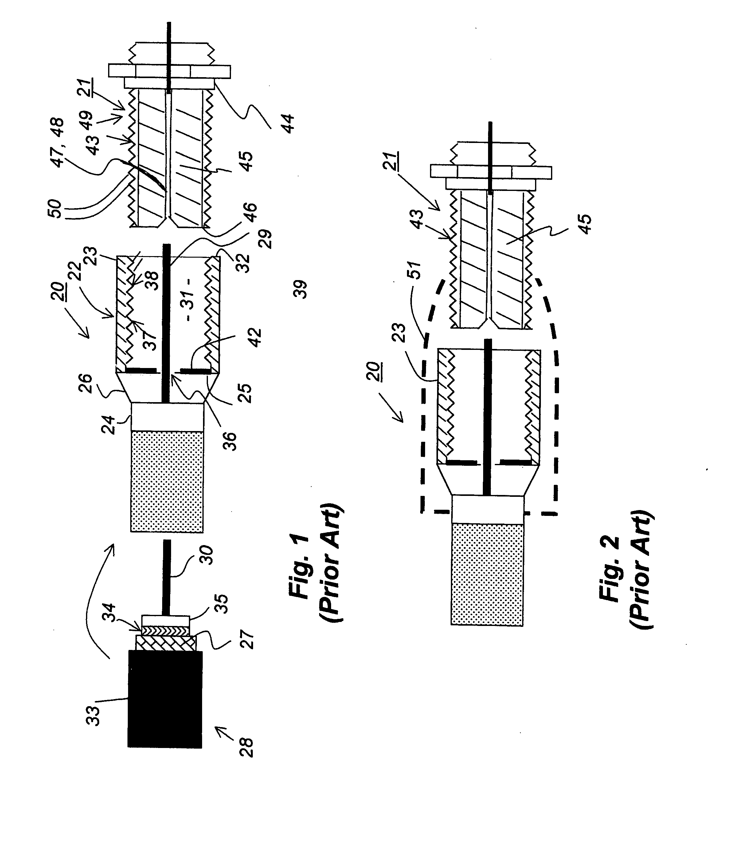
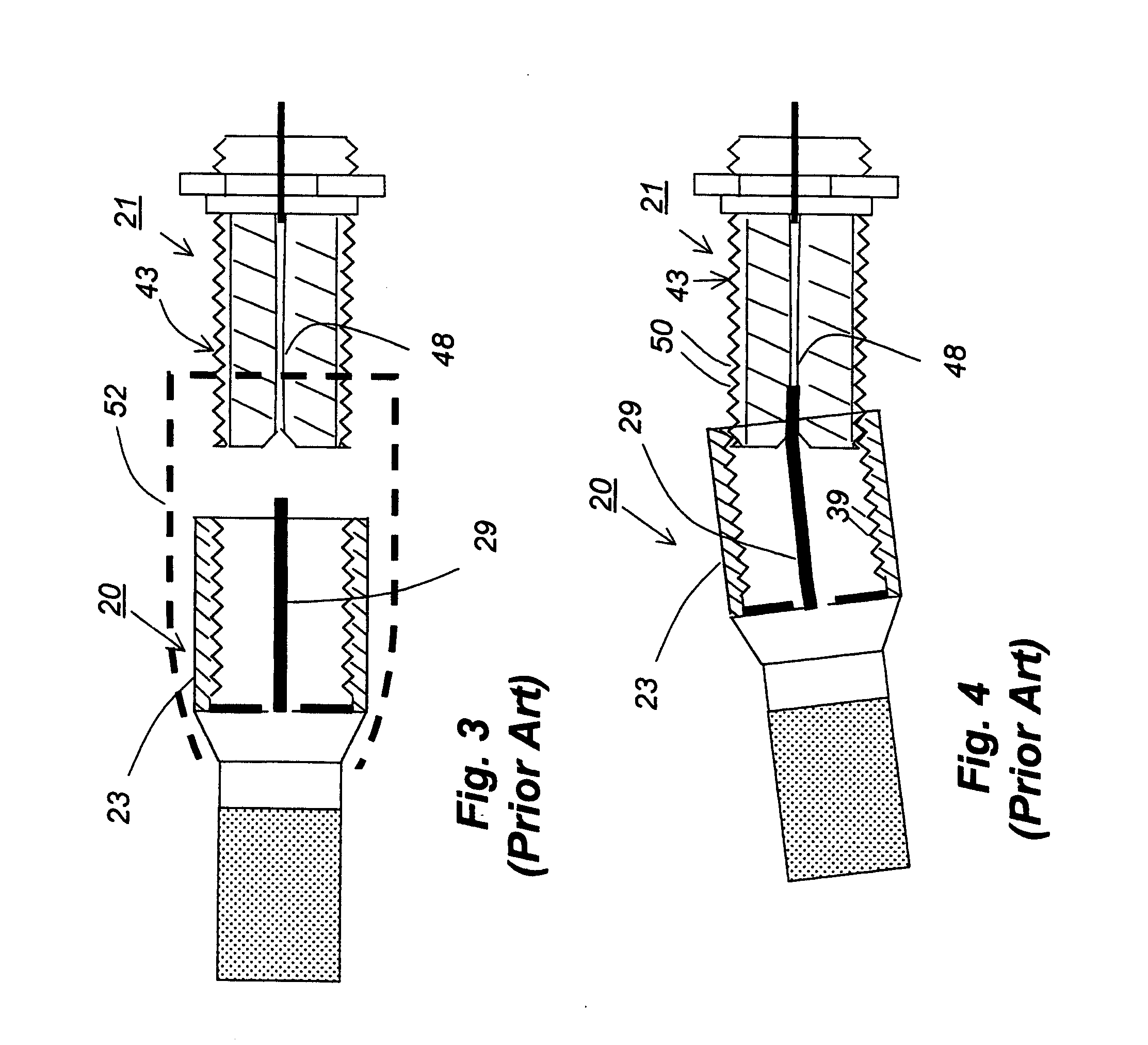
[0046]FIGS. 1-5 illustrate a prior art fully-threaded male coaxial connector 20 and a prior art female coaxial connector 21 which is adapted to mate with connector 20. As shown in FIG. 1, male connector 20 includes a cylindrically-shaped tubular body 22 that has a front elongated tubular section 23 made of an electrically conductive material such as nickle plated zinc. Body 22 includes a short rear tubular section 24 of smaller diameter than front tubular section 23 which is joined at a rear annular flange 25 of the front tubular section by an annular transition section 26. Rear tubular section 24 is in electrically conductive contact with transition section 26 and front tubular section. Typically, the foregoing sections of connector 20 are made from a single piece of metal tube stock.

[0047]Rear tub...


PUM


Abstract

Male and female reduced thread coaxial connectors for interconnecting center and outer conductors of pairs of coaxial signal lines each has a rear tubular connector body section for attachment in electrically conductive contact to the outer conductor of a coaxial cable and a front cylindrically shaped body section which is in electrically conductive contact with the rear body section and protrudes axially forward therefrom. The front body section of the male reduced thread connector has a longitudinally disposed bore, the circumferential wall surface of which has in a rear portion thereof helical threads adapted to threadingly engage threads on an outer cylindrical surface of the front connector body section of a standard fully threaded female coaxial connector, and a front unthreaded portion which is adapted to insertably receive the front female connector body section and thereby guide the axes of the female and the male connectors into alignment prior to mutual contact of their threaded surfaces. The front body section of the reduced thread female connector has an outer cylindrical wall surface which has in a rear portion thereof helical threads adapted to threadingly engage helical threads of a standard fully threaded male connector, and a front unthreaded portion which is adapted to be inserted into the bore of the male connector body section and thereby guide the axes of the male and female connectors into axial alignment prior to mutual contact of their threaded surfaces.

Description

[0001]The present application claims priority to U.S. provisional patent application No. 60,873,810, filed on Dec. 9, 2006 by the present inventor.BACKGROUND OF THE INVENTION[0002]A. Field of the Invention[0003]The present invention relates to connectors for use with coaxial cables used to carry high frequency analog signals such as video, television, satellite signals, and high-speed digital data signals. More particularly, the invention relates to a coaxial connector of novel design which facilitates connecting and disconnecting the connector to target mating connectors of various types, with greater speed and less likelihood of mis-aligning or cross-threading the target connector than possible with pre-existing connectors.[0004]B. Description of Background Art[0005]There are available a variety of connector types for connecting the conductors of a coaxial electrical signal cable with corresponding conductors of another cable or with an electronic device such as a satellite or tel...

Claims


Application Information

Patent Timeline
IPC IPC(8): H01R9/05
CPCH01R13/622H01R9/0521
Inventor HO, KESSE C.
Owner HO KESSE C
Why Eureka
Try Eureka