
Heated separation vessel for well fluids

a separation vessel and well fluid technology, applied in the direction of fire-tube steam boilers, fluid removal, insulation, etc., can solve the problems of increasing the heating requirement, increasing the difficulty of the typical natural draft burner system to meet such new standards, and increasing the government regulations. , to achieve the effect of more rapid and efficient heating of the fluid being separated

Inactive Publication Date: 2008-06-12
UNIVERSAL INDS CORP
View PDF5 Cites 3 Cited by
  • Summary
  • Abstract
  • Description
  • Claims
  • Application Information

AI Technical Summary

Benefits of technology

[0007]It is an object of the present invention to provide in a separation vessel a heating system which provides more rapid and efficient heating of the fluids being separated without emitting significant greenhouse gases.

Problems solved by technology

Over the past decade or so, however, the separating vessels have become much larger causing the heating requirement to significantly increase, and as a result, it is difficult in many operations for the field facilities to provide enough fuel gas to fire larger burners of the type used in the past.
Furthermore, government regulations have become more strict to the point it is difficult for the typical natural draft burner systems to meet such new standards.
Also, due to the nature of the known natural draft systems, which must utilize very large firetube diameters, such systems are known to encounter severe leakage characteristics and overall produce high amounts of greenhouse gases.

Method used


Image

  • Heated separation vessel for well fluids
  • Heated separation vessel for well fluids
  • Heated separation vessel for well fluids

Examples


Embodiment Construction

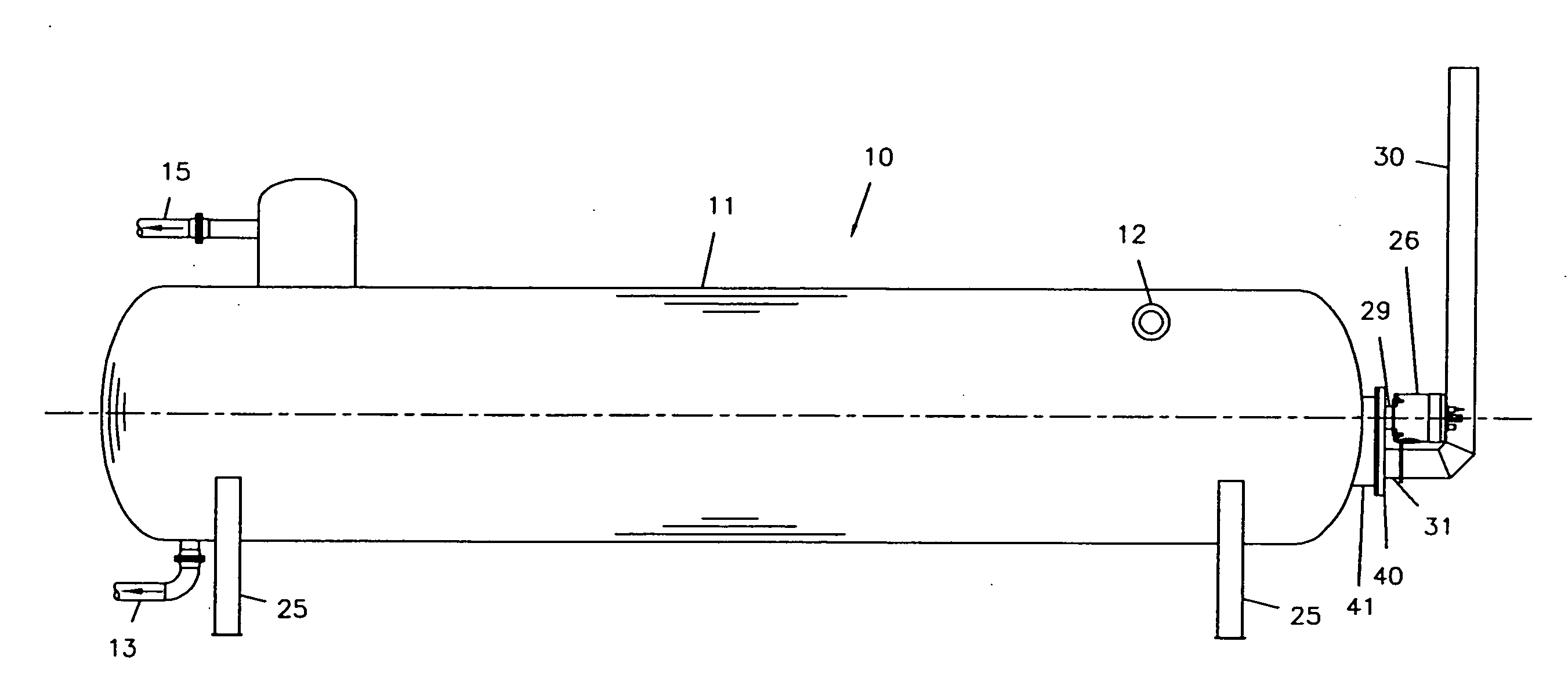
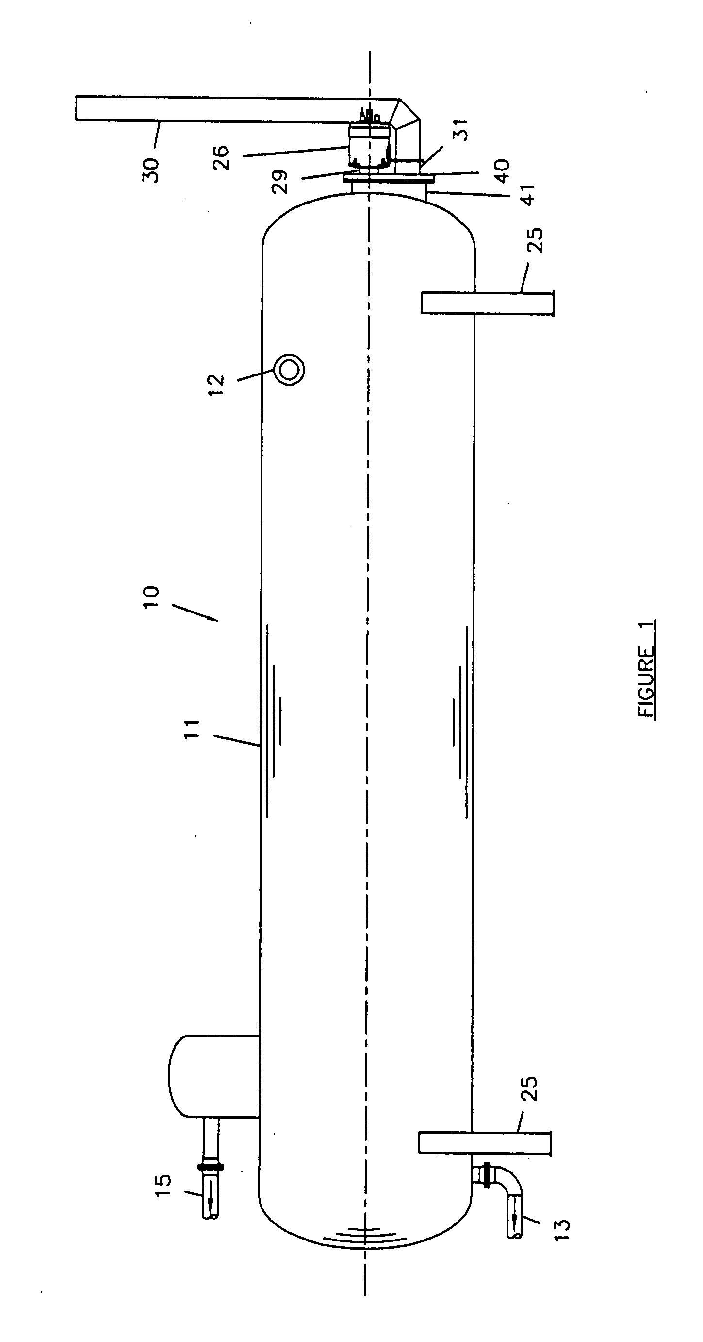
[0014]Referring first briefly to FIG. 1, it can be seen that there is present a separating unit 10 formed by an elongated, sealed vessel 11 of circular cross section to which is transferred from an adjacent well (not shown) production material which normally consists of oil, water, natural gas, and possibly other impurities through vessel pipe 12. After entering the vessel, the production materials flow towards the opposite end of the vessel during which separation of the constituents of well production occurs. Eventually, the fluids leave the vessel through separate outlets which includes oil and gas outlets shown as 13 and 15, respectively.

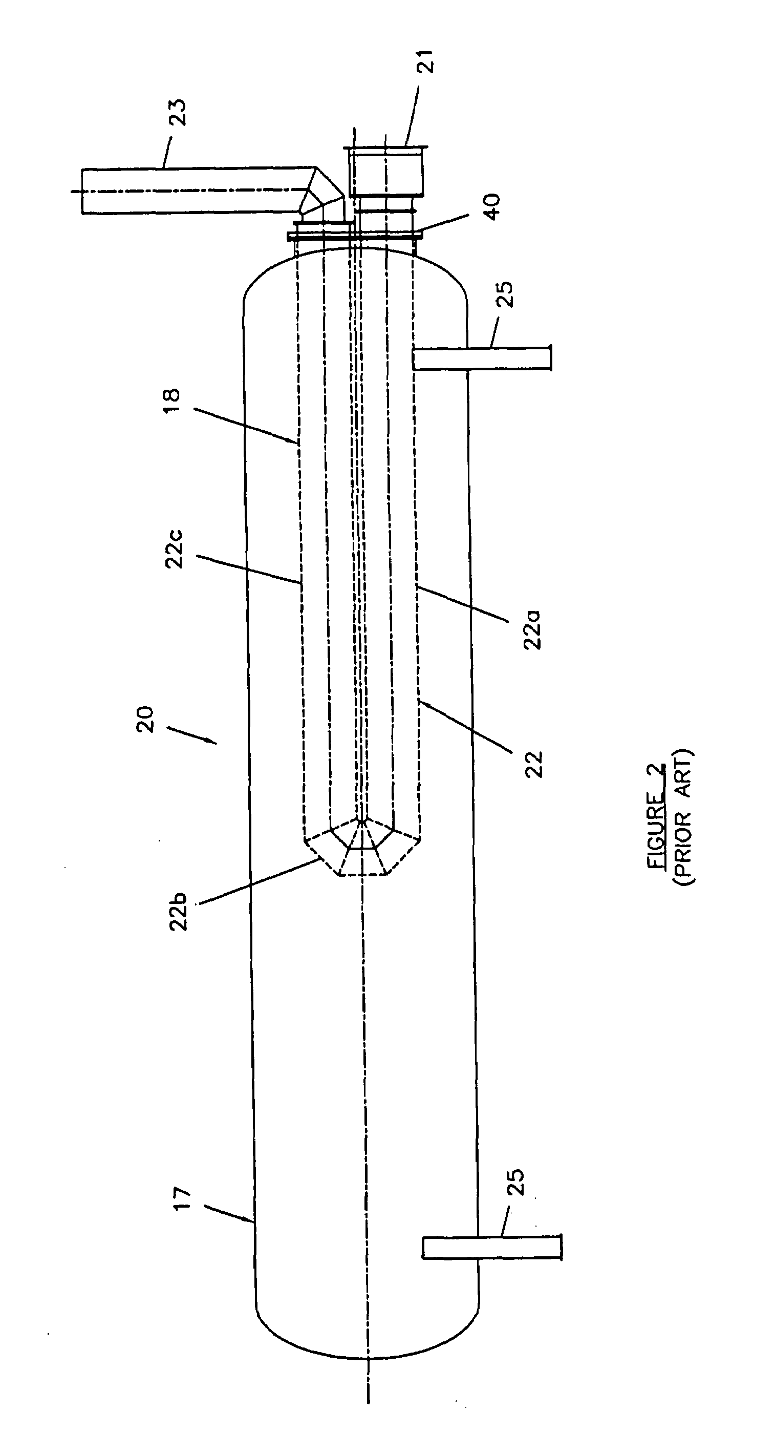
[0015]Returning now, however, to the features of the conventional natural draft burner system, reference is made to FIG. 2 of the drawings, wherein such a burner system is shown for adding heat to the separation process generally designated 17. The heating system thereof is generally designated 18 contained in an elongated separation vessel 20. ...


PUM

PropertyMeasurementUnit
heat toaaaaaaaaaa
lengthsaaaaaaaaaa
lengthaaaaaaaaaa

Abstract

An apparatus and method for separating the output fluids of a well by way of efficiently applying heat to the fluids. Separation takes place in a sealed vessel to which heat is applied to the fluid by contact with a multi-pass firetube assembly through which hot exhaust gas is expelled from a forced draft burner. The firetubes forming the assembly are of smaller diameter than used in conventional separators and not subject to high leakage experienced in conventional separating vessels, and the heat transfer is highly efficient resulting in less fuel consumption and less emission of greenhouse gases.

Description

CROSSED REFERENCE TO RELATED APPLICATION[0001]This application claims the benefit of convention priority on Canadian Patent Application No. 2,570,719, filed Dec. 8, 2006 entitled Heated Separation System For Well Fluids.FIELD OF THE INVENTION[0002]This invention relates to the gravity treating of fluid such as produced oil and water from a well, and more particularly, to a heating system for applying heat to the fluids to enhance separation.BACKGROUND OF THE INVENTION[0003]Various types of separation systems are presently used in oil field facilities at the well head where oil, water and natural gas occur together naturally.[0004]A common type of such a system uses a treating vessel wherein the produced fluids of a well slowly travel through the vessel in order to basically allow the water to sink and the oil to float. The fluid properties determine the amount of resident time required for separation. Baffles and the like along the path of flow are commonly used to enhance this proc...

Claims


Application Information

Patent Timeline
Patent Type & Authority Applications(United States)
IPC IPC(8): E21B36/02B01D35/00B01D35/18F22B9/00E21B36/00
CPCB01D17/042B01D17/0208
Inventor UNRAU, LES
Owner UNIVERSAL INDS CORP
Learn More