
Assembled Prosthesis Such as a Disc

Inactive Publication Date: 2008-06-05
KYPHON
View PDF9 Cites 159 Cited by
  • Summary
  • Abstract
  • Description
  • Claims
  • Application Information

AI Technical Summary

Benefits of technology

[0013]A potential advantage of in situ assembly is the ability to implant the artificial disc using a minimally invasive procedure, through a relatively minor port into the body, and thus potentially reducing the damage to surrounding tissue and spinal stability, simplifying the operation and / or facilitating recovery.
[0018]In an exemplary embodiment of the invention, each prosthesis portion comprises corresponding slices of the two plates, which are inserted together, loaded on a single delivery system / inserter. In an exemplary embodiment of the invention, the assembly of adjacent portions is enabled by a locking mechanism, for example of a male-female type, which may also enable insertion of one prosthesis portion over the side of its adjacent, previously inserted, portion. In additional embodiment of the invention, the locking mechanism between adjacent portions of the prosthesis prevents relative motion between prosthesis portions in all planes.
[0021]In an exemplary embodiment of the invention, the design of the artificial disc enables a relative motion between the two plates, to restore motion and stability of the affected spinal segment. In additional embodiment of the invention, the design of the artificial disc allows for disc height restoration, for example by providing a vertical dimension similar to or greater than that of a natural disc being replaced.
[0023]In an exemplary embodiment of the invention, at least one of the two metal endplates are coated, for instance with hydroxyapatite (HA) or titanium plasma spray, to enhance osteointegration and / or improve plates connection to adjacent vertebrae.
[0027]In an exemplary embodiment of the invention, an instrumentation set is provided, intended to assist minimal invasive deployment and / or assembly of a prosthesis as described herein.

Problems solved by technology

Trauma, spinal diseases (such as degenerative disc disease) and normal aging processes may damage the intervertebral disc.
For example, a weakening or tear of the annulus fibers may lead to disc herniation, as the nucleus extrudes out of its location inside the annulus ring.
This mass extrusion can mechanically press on neighboring spinal nerves, resulting in back pain, radiation pain, loss of muscle control and even paralysis.
The only temporary success of discetomy is probably due to continuation of the degenerative process, segmental instability and spinal stenosis.
A decrease in the disc height is quite common after discectomy, and might result in size decrease of the neural foramina, alteration of facet loading and function, as well as adverse effect on sagittal balance.
However, long-term results indicate that numerous patients develop recurrent symptoms years after surgery.
In addition, the procedure causes permanent loss of function and mobility of the involved segment.
It also perturbs the biomechanics of adjacent vertebral levels, and may induce more rapid degeneration of adjacent segments.
Furthermore, most of the devices intended for implantation during vertebral fusion require highly invasive surgical technique, resulting in damaging of the surrounding tissue, including bone structure sacrifice that may compromise spinal stability.
; the Prodisc, by Spine Solutions / Synthes; the Maveric, by Medtronic Sofamor Danek; and the FlexiCore, by SpineCore—all of which are implanted in a relative invasive surgical techniques, normally in an open anterior approach, which require a large insertion aperture and may lead to risks and complications thereof.

Method used


Image

  • Assembled Prosthesis Such as a Disc
  • Assembled Prosthesis Such as a Disc
  • Assembled Prosthesis Such as a Disc

Examples


Embodiment Construction

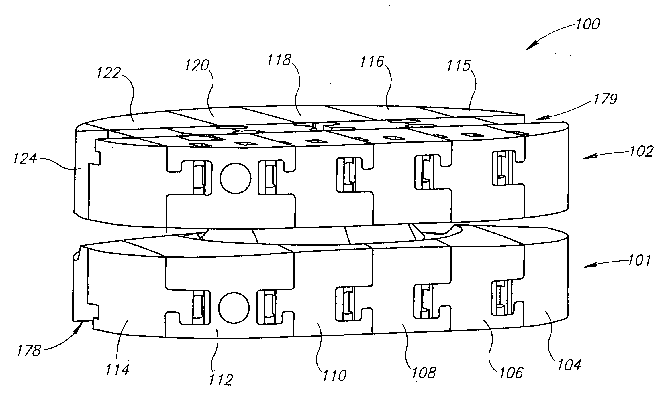
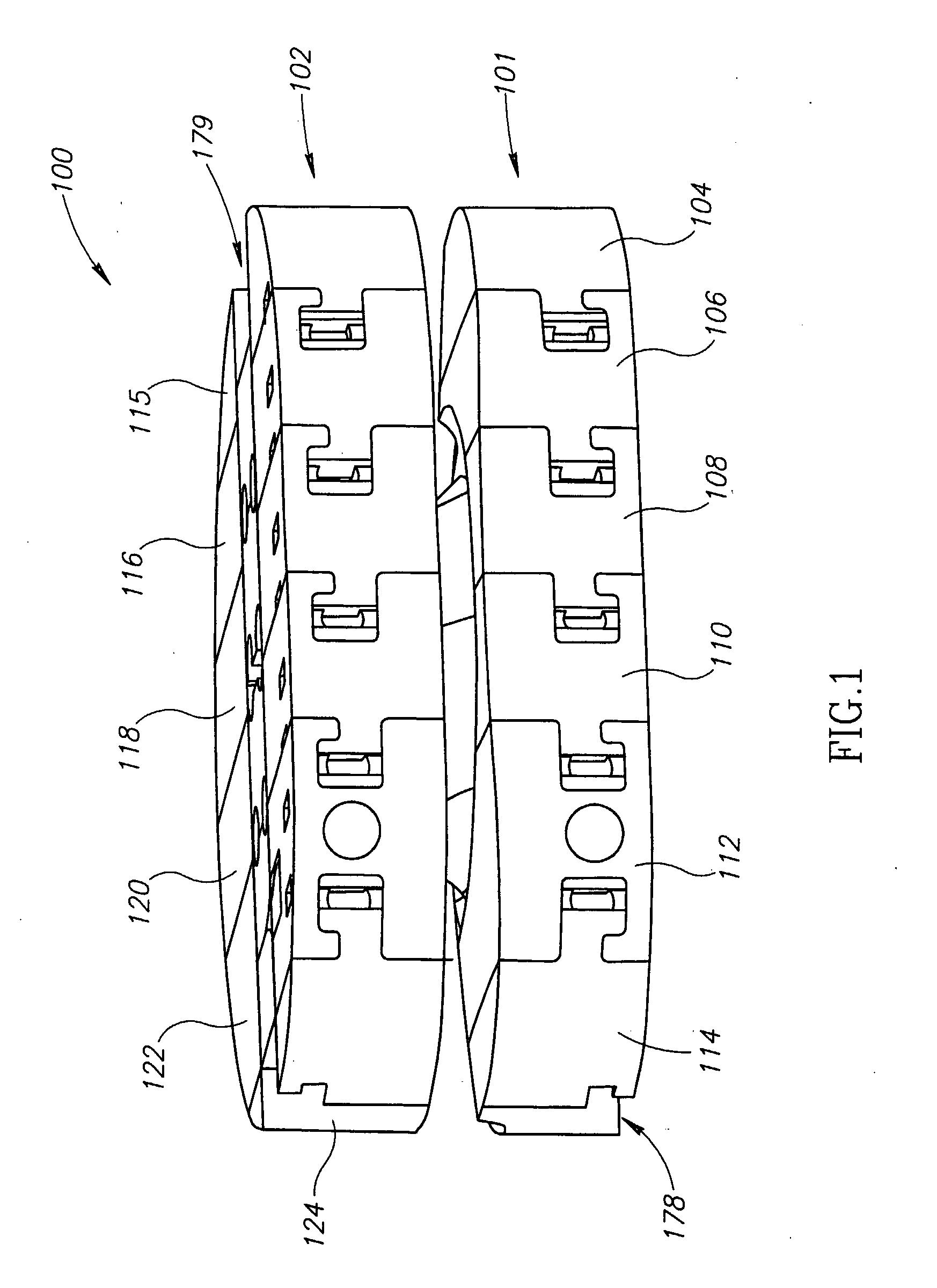
[0077]FIG. 1 illustrates a disc prosthesis 100, comprising an inferior plate 101 and a superior plate 102, in accordance with an exemplary embodiment of the invention. The two plates 101, 102 have a same circumference / contour line, although different dimensions and / or shapes for each of the two plates 101, 102 may be provided in some embodiments of the invention. Each plate 101, 102 is composed of six slices 104-114, 115-124, respectively. Other number of slices may be provided and, in general, the number of plate slices and their cross-sections may depend on disc size and / or the disc's location. The plates 101, 102 may be connected to their adjacent vertebral endplates by protrusions (not shown in FIG. 1), for example protrusions that project from a slot (or a windowing element) 178, 179 in each plate 101, 102, respectively, toward endplates of adjacent vertebrae and penetrate them following prosthesis insertion, for example, to prevent prosthesis migration.

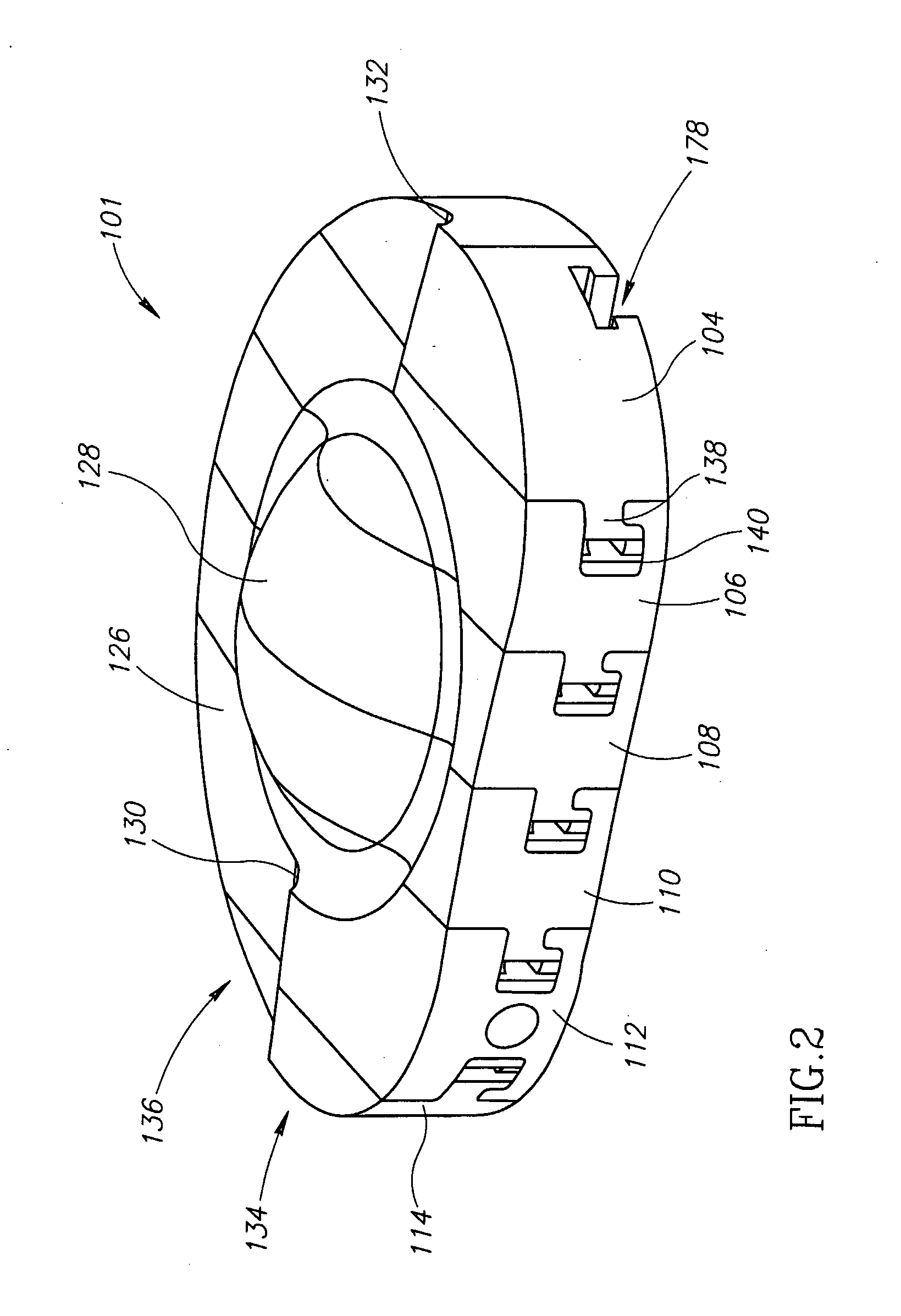
[0078]FIG. 2 shows lower...


PUM

PropertyMeasurementUnit
Diameteraaaaaaaaaa
Diameteraaaaaaaaaa
Areaaaaaaaaaaa

Abstract

An artificial disc device, comprising a plurality of interconnected elements, adapted to be assembled in situ.

Description

RELATED APPLICATIONS[0001]The present application is a US National Phase of PCT Application No. PCT / IL2005 / 001198, filed on Nov. 15, 2005, published as WO 2006 / 051547. This application is based upon and claims the benefit under 35 USC 119(e) of U.S. provisional patent application Ser. No. 60 / 627,141, filed Nov. 15, 2004, the disclosures of which are incorporated herein by reference in their entirety.FIELD OF INVENTION[0002]The present invention relates to a prosthesis device, for example one used in a minimally invasive method for replacing a damaged intervertebral disc.BACKGROUND OF THE INVENTION[0003]The vertebral bodies of the spine are connected to one another by a disc. The intervertebral discs give the column its flexibility and mobility. Each intervertebral disc comprises a nucleus pulposus (“nucleus”) surrounded by the annulus fibrosus (“annulus”). The latter binds together adjacent vertebrae, and is composed of multiple and overlapping layers of concentric, collagen fiber r...

Claims


Application Information

Patent Timeline
IPC IPC(8): A61F2/44
CPCA61F2002/30919A61F2002/30904A61F2002/4627A61F2002/4629A61F2002/4635A61F2210/0004A61F2210/0014A61F2220/0025A61F2220/005A61F2220/0075A61F2230/0069A61F2/4425A61F2/4611A61F2002/30062A61F2002/30092A61F2002/30224A61F2002/30387A61F2002/30448A61F2002/30462A61F2002/305A61F2002/30563A61F2002/30565A61F2002/30574A61F2002/30579A61F2002/30604A61F2002/30616A61F2002/30738A61F2002/30884A61F2002/443
Inventor BEYAR, MORDECHAYGLOBERMAN, OREN
Owner KYPHON
Learn More