Apparatus and Method for Imaging the Relative Motion of Skeletal Segments

a technology of relative motion and skeletal segments, applied in the field of automatic system for monitoring the movement of bones in the skeleton, can solve the problems of preventing accurate diagnosis and informed treatment, unable to assess the functional integrity of joints, especially spinal joints, without invasive procedures, etc., and achieve the effect of minimal invasiveness

Inactive Publication Date: 2008-05-29
AECC ENTERPRISES
View PDF99 Cites 25 Cited by
  • Summary
  • Abstract
  • Description
  • Claims
  • Application Information

AI Technical Summary

Benefits of technology

[0006]The present invention makes it immediately possible to use x-ray intensifier technology, or its successors (e.g. real-time magnetic resonance or other imaging), to carry out these procedures by objectively measuring the functional integrity of joint tissues with a minimum of invasiveness. Its immediate application is to the detection of failed spinal fusions, avoiding the necessity for a second operation to inspect the integrity of the original graft.

Problems solved by technology

Examining this integrity for the purpose of understanding malfunction in the living organism, without penetrating the surface, has hitherto been an insurmountable problem, preventing accurate diagnosis and informed treatment.
This has meant that the functional integrity of joints, especially the spinal joints, could not be assessed in living subjects without resorting to invasive procedures.
Spinal fusions, often a last resort for intractable back pain, could not be inspected for their success without revision surgery, and suspected disruption of ligaments could not be objectively assessed.
Attempts to overcome this difficulty by placing measuring devices on the surface of body segments, and recording their displacements during movement of the body were unsatisfactory because it was surface (skin) rather than bone motion that was recorded—especially in relation to the segments of the spine.
The use of plain X-rays was also unsatisfactory because only the beginning and end of the motion could be recorded without giving a prohibitive radiation dose.
Furthermore, marking a sufficient number of the images in a motion sequence manually, in pursuit of such measurement, was too laborious to support a method for use in clinical settings.

Method used


Image

  • Apparatus and Method for Imaging the Relative Motion of Skeletal Segments
  • Apparatus and Method for Imaging the Relative Motion of Skeletal Segments
  • Apparatus and Method for Imaging the Relative Motion of Skeletal Segments

Examples


example 1

Imaging of a Patient with Intractable Spinal Pain

[0071]Data Acquisition

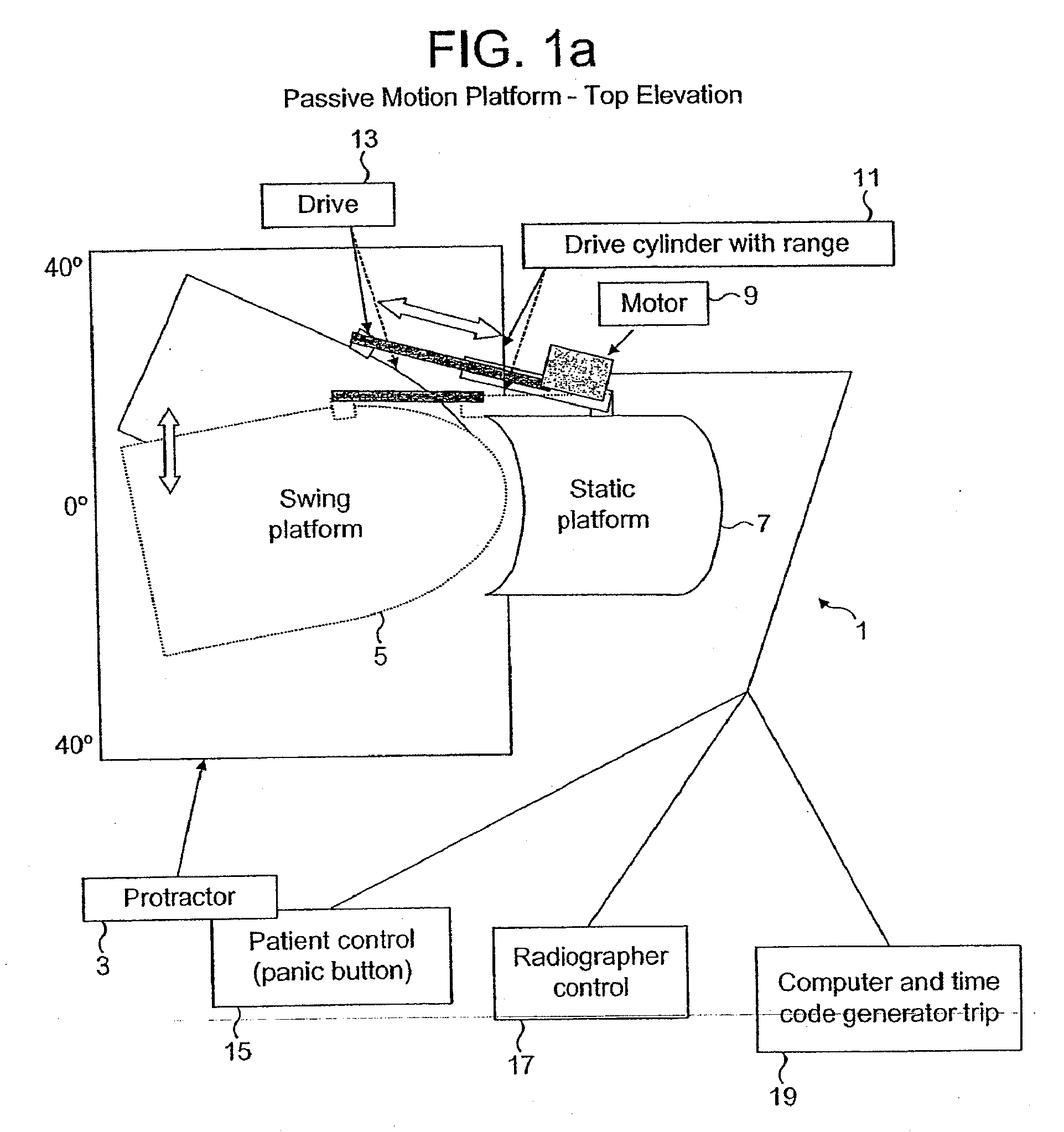
[0072]Typically, a patient with chronic intractable spinal pain will be referred for the investigation. The patient will normally attend the X-ray department as an outpatient and will enter an imaging suite under the direction of a radiographer and an assistant. All components of the device, which is portable, will be in place when the patient enters.

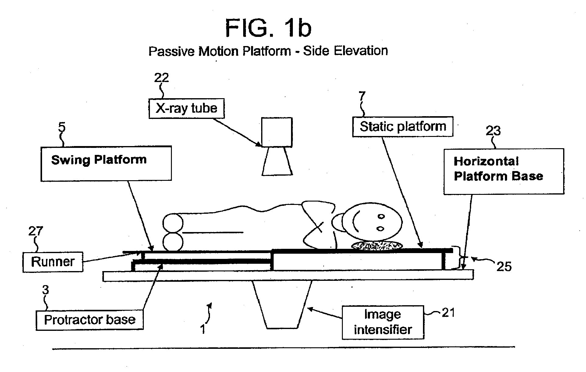
[0073]The patient will be familiarised with the action of the passive motion platform by demonstration and then will be helped to lie on it in the prone or supine position. The swing platform will be moved and the patient's acceptance of the motion determined. The range of motion achievable will be decided by discussion and tested without imaging to ensure it is well tolerated. Devices for gonadal protection and the reduction of any intensifier flare will then be placed on the passive motion platform.

[0074]The radiographer will centre the level of interest and config...

example 2

An Objective Spinal Imaging Assessment of the Integrity of Lumbar Spine Stabilisation Grafts

[0084]The prospect of a second operative procedure following an apparently unsuccessful spinal fusion is an unwelcome one. The method of the present invention described herein combines sufficiently reduced operator interaction with acceptable error limitation to be operationally useful as a tool for reporting findings about graft integrity for spinal surgeons.

[0085]Methods and results: The measurement of lumbar inter-vertebral coronal and saggital plane motion ii: vivo using this technique is in 3 stages:

[0086]Fluoroscopic screening of patients lying on a passive motion table

[0087]Co-ordinated real-time digital acquisition of the intensifier images.

[0088]Registration of the images of each vertebra by templates which are automatically tracked and whose output is converted to inter-vertebral kinematic parameters and averaged for display and reporting.

[0089]Results are currently displayed as int...


PUM


Abstract

Apparatus provided for the measurement of skeletal joint motion in a subject which comprises a passive motion device, an imaging device and a processing system incorporating a means for real time digital sampling of images of moving joints, means for recognising templates attributed to individual bones and tracking these automatically using cross-correlation functions and means for geometric transformation of the positional data to graphically display their relative motion over time. Also provided is a method for the automated measurement of the relative motion of skeletal structures in vivo using such apparatus and a method for the diagnosis of a pseudoarthrosis in a subject which comprises the use of such apparatus.

Description

CROSS-REFERENCE[0001]This application is a continuation of application Ser. No. 10 / 520,489, filed Jul. 8, 2003, which claims the benefit of PCT / GB03 / 02934 filed on Jul. 8, 2003, which claims priority to Great Britain Patent Application 0215848.3 filed Jul. 9, 2002 and Great Britain application 0226264.0 filed Nov. 11, 2002.FIELD OF THE INVENTION[0002]The present invention relates to an automated system for monitoring the movement of bones in the skeleton of a subject, with particular reference to the bones in patients after surgery.BACKGROUND OF THE INVENTION[0003]The skeleton is the support system of land animals and its joints are key to its structural integrity in everyday life. Examining this integrity for the purpose of understanding malfunction in the living organism, without penetrating the surface, has hitherto been an insurmountable problem, preventing accurate diagnosis and informed treatment. This has meant that the functional integrity of joints, especially the spinal jo...

Claims


Application Information

Patent Timeline
IPC IPC(8): A61B5/11A61B6/00H05G1/00A61B5/05A61B5/055A61B6/04
CPCA61B5/0555A61B5/11A61B5/1128A61B5/4504A61B5/704A61B6/04G06T7/0012A61B6/508A61B5/4528A61B5/055A61B6/50G06T2207/10116G06T2207/30004G06T2207/10088G06T7/20G06T2207/30008
Inventor BREEN, ALAN
Owner AECC ENTERPRISES
Why Eureka
Try Eureka