
Pseudo digital gain control for broadband tuner

a broadband tuner and gain control technology, applied in the field of gain control circuits, can solve problems such as signal distortion, improper operation of subsequent circuitry and devices receiving signals, and subsequent demodulator circuits that may not operate properly when subjected, so as to simplify the overall circuit design, reduce circuitry, and increase bandwidth

Active Publication Date: 2008-05-29
CSR TECH INC
View PDF8 Cites 5 Cited by
  • Summary
  • Abstract
  • Description
  • Claims
  • Application Information

AI Technical Summary

Benefits of technology

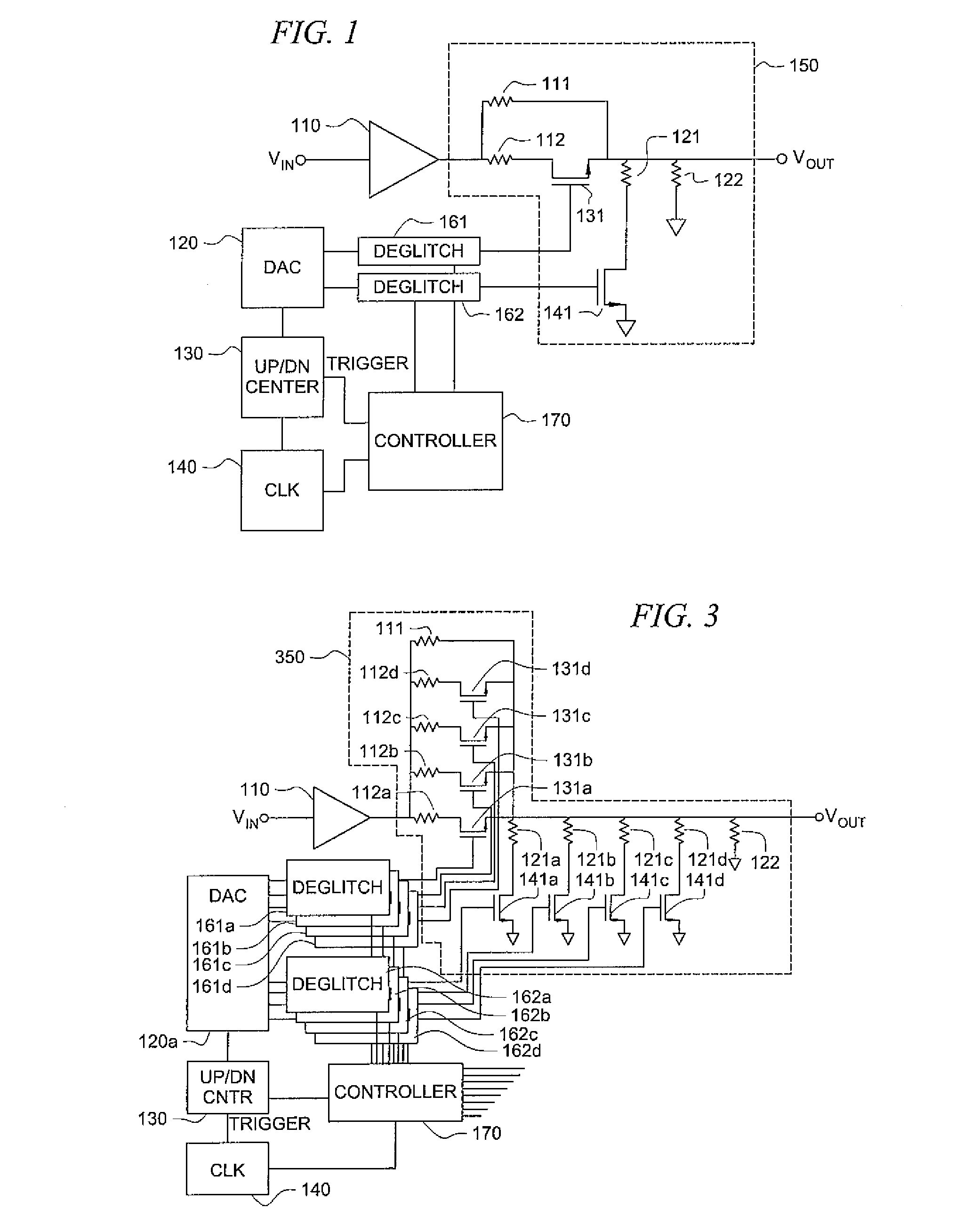
[0013]One of the advantages of various embodiments of the invention is an overall reduction in circuitry required in comparison, for example, to requiring a large number of digitally settable levels to avoid large level transitions. Avoiding near instantaneous level changes simplifies overall circuit design, supports higher bandwidths, and avoids other design issues. For example, when integrated into a television tuner, circuit design is simplified by avoiding instantaneous signal level changes that might cause a demodulator to malfunction or cause performance problems in the system. According to one embodiment of the invention, a time period over which a level transition occurs may be programmable so that a resultant circuit gain change is essentially linear from one large step to another large step over a predetermined amount of time and / or at some constant rate. Other methods of moderating signal change level may also be implemented such as a specified dv / dt or di / dt maximum.

Problems solved by technology

If not moderated, allowing large steps in signal levels can result in signal distortion and improper operation of subsequent circuitry and devices receiving the signal.
For example, if part of an automatic gain control circuit (AGC) such as in a television tuner or receiver, a subsequent demodulator circuit may not operate properly when subjected to large near-instantaneous level changes of a signal to be processed.

Method used


Image

  • Pseudo digital gain control for broadband tuner
  • Pseudo digital gain control for broadband tuner
  • Pseudo digital gain control for broadband tuner

Examples


Embodiment Construction

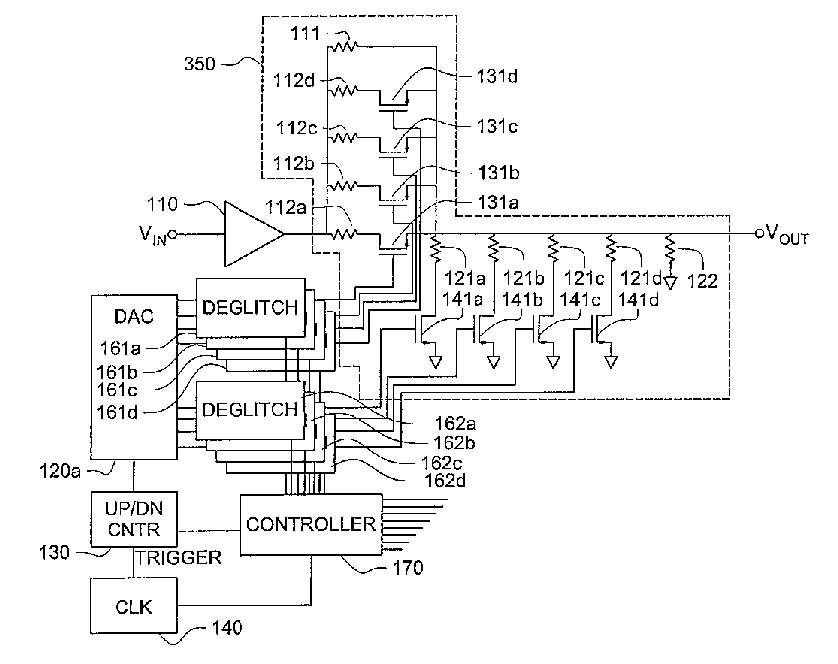
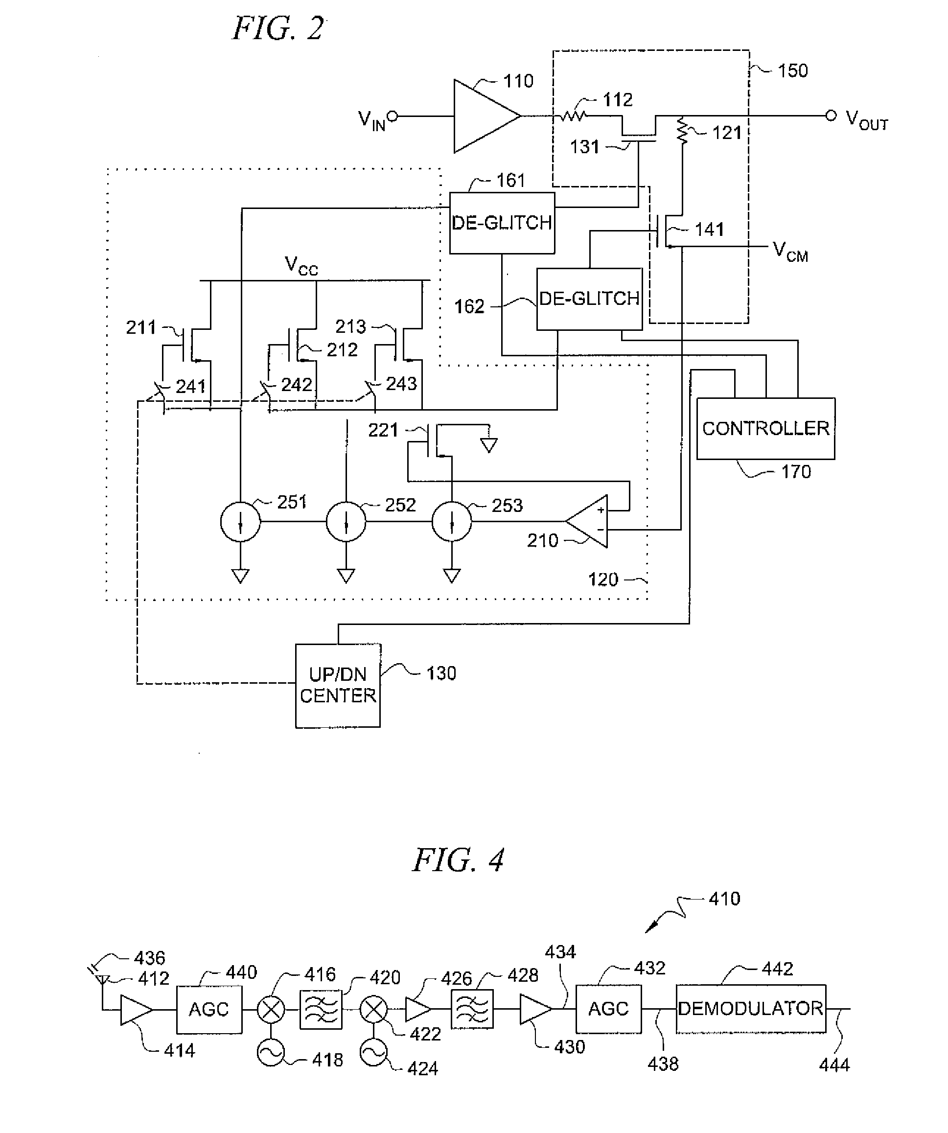
[0020]FIG. 1 is a circuit diagram of an automatic gain control circuit (AGC) implemented as switched output Attenuator 150 having switching elements in the form of FETs 131 and 141 controlled by an incremental step moderating circuit according to an embodiment of the present invention. The moderating circuit including DAC 120, Up / Down Counter 130, Clock 140, Deglitch Circuits 161, 162 and Controller 170 that act in concert to cause the switching elements to gradually turn on or off over some transition period of gradual or stepwise increasing or decreasing conductance levels. Thus, within the larger intervals between levels selectable or settable by turning FETs 131 and 141 completely on and off, the moderating circuitry implements a sequence of smaller, “sub-interval” stepped or incremental transitions that more gradually change the signal level output while transition between selectable / programmable levels during some transition period.

[0021]Controller 170 includes logic in the fo...


PUM


Abstract

A digital level control circuit, such as an Automatic Gain Control, includes a plurality of digitally selectable signal levels with transitions between levels gradually varied to avoid signal output level discontinuities. An up / down counter may be used to incrementally stepwise transition an output signal between the digitally selectable output levels. Stepwise application of a control signal to the appropriate switching elements (e.g., FETs) forming an attenuator circuit may be implemented to moderate a switching time of the switching elements to provide a more gradual transition between element operating states. A deglitch circuit may be employed to latch the switching elements to achieve the desired state at the end of a desired switching transition period.

Description

CROSS-REFERENCE TO RELATED APPLICATIONS[0001]The presented application is related to and incorporates by reference herein in their entireties the disclosures of U.S. patent application Ser. No. 11 / 376,745 filed Mar. 15, 2006 and entitled Broadband Integrated Tuner; U.S. patent application Ser. No. 08 / 426,080 filed Apr. 21, 1995, now U.S. Pat. No. 5,737,035 and entitled Highly Integrated Television Tuner on a Single Microcircuit; U.S. patent application Ser. No. 08 / 904,908 filed Aug. 1, 1997, now U.S. Pat. No. 6,177,964 and entitled Broadband Integrated Television Tuner; and U.S. patent application Ser. No. 09 / 572,393 filed May 16, 2000 and entitled Broadband Integrated Tuner.TECHNICAL FIELD[0002]The invention generally relates to gain control circuits and more particularly to automatic gain control mechanisms and methods for use with or forming a part of circuits such as tuner circuits.BACKGROUND OF THE INVENTION[0003]Automatic gain control (AGC) is an electronic system found in man...

Claims


Application Information

Patent Timeline
Patent Type & Authority Applications(United States)
IPC IPC(8): H04B1/18H03G3/30
CPCH03G3/001H03G1/0088
Inventor MAGNUSEN, TIMOTHY M.
Owner CSR TECH INC
Learn More