
Catalytic oxide anodes for high temperature fuel cells

a fuel cell and catalytic oxide technology, applied in the field of fuel cells, can solve the problems of limiting the optimal operational output, deficiency of one element, and difficult material selection for catalytic anodes, and achieve the effects of enhanced catalytic activity, enhanced electronic conductivity and oxygen vacancy formation

Inactive Publication Date: 2008-05-29
DIRECT CARBON TECH
View PDF6 Cites 7 Cited by
  • Summary
  • Abstract
  • Description
  • Claims
  • Application Information

AI Technical Summary

Benefits of technology

[0019]In yet another aspect of this embodiment, the B site of the anode material doped with transition metals selected from among the elements V, Cr, Mn, Fe, Co, Ni, Rh, Cu, Zn, Ag, Pt, and Pd whereby catalytic activity, electronic conductivity and oxygen vacancy formation are enhanced.

Problems solved by technology

In applications for direct carbon fuel cells (DCFC), suitable materials for catalytic anodes remain a difficult problem when considering the commercialization of these technologies.
The anodes in these fuel cells are subject to harsh environments that cause degradation in the anode, thus limiting optimum operational output.
Often, they are solids that contain random crystallographic point defects, resulting in the deficiency of one element.
However, there is a knowledge gap, especially in the case of DCFC.
Cracking catalysts employed in the chemical and petrochemical industries provide limited guidance but again, the mechanism of breaking C—C bonds in a carbon or coal particle is significantly different from breaking C—H and C—C bonds in a hydrocarbon molecule.

Method used


Image

  • Catalytic oxide anodes for high temperature fuel cells
  • Catalytic oxide anodes for high temperature fuel cells

Examples


Embodiment Construction

[0024]Although the following detailed description contains many specifics for the purposes of illustration, anyone of ordinary skill in the art will readily appreciate that many variations and alterations to the following exemplary details are within the scope of the invention. Accordingly, the following preferred embodiment of the invention is set forth without any loss of generality to, and without imposing limitations upon, the claimed invention.

[0025]The current invention provides an anode material having high catalytic activity and selectivity for carbon oxidation, sufficient oxygen non-stoichiometry, rapid oxygen chemical diffusion, wide thermodynamic stability window to withstand reducing environment, sufficient electronic conductivity and tolerance to sulfur and CO2 environments.

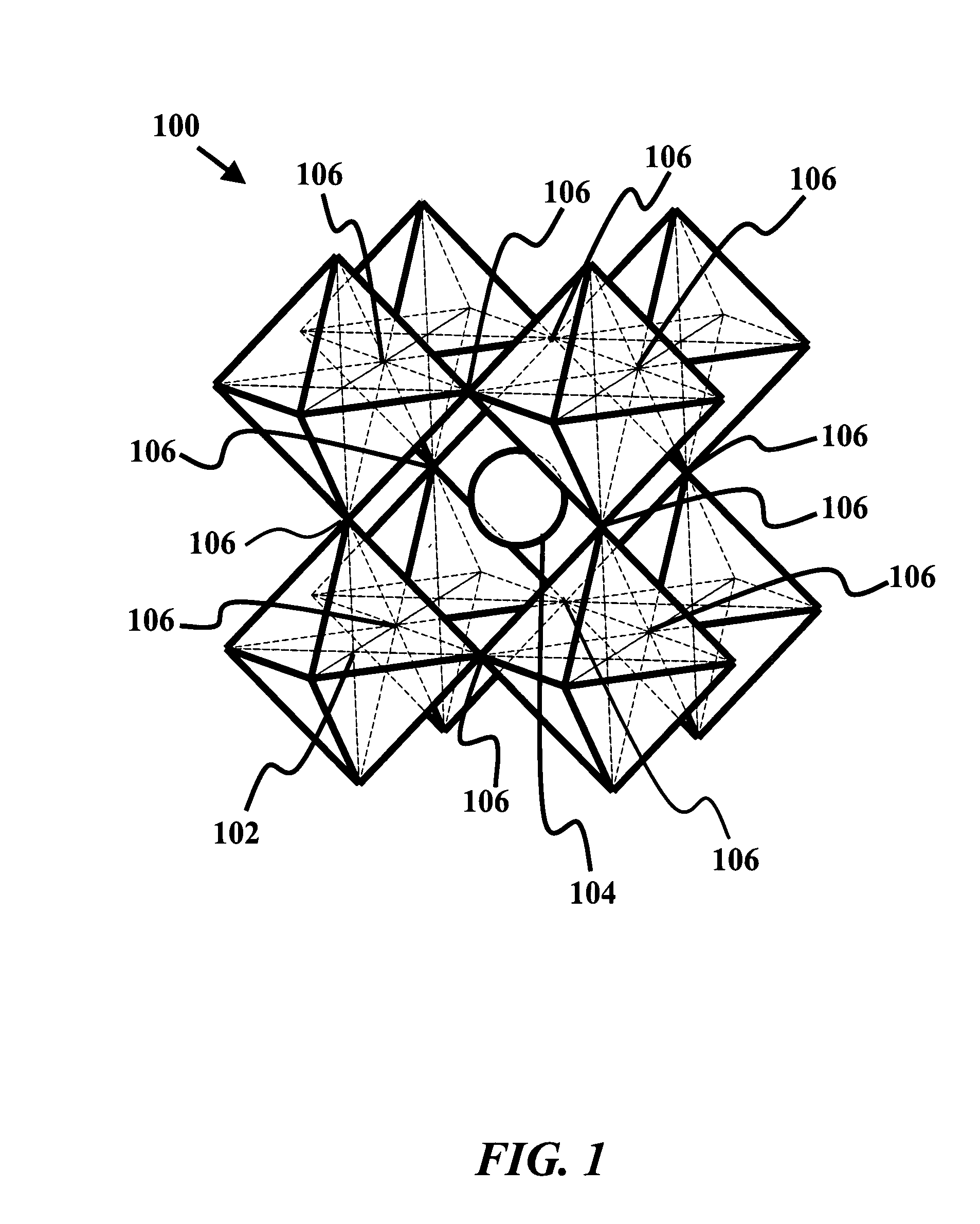
[0026]Perovskites consist of a rich family of oxides interesting properties, especially when doped properly. Many members of the perovskite family have been employed as active catalysts for a wide ra...


PUM


Abstract

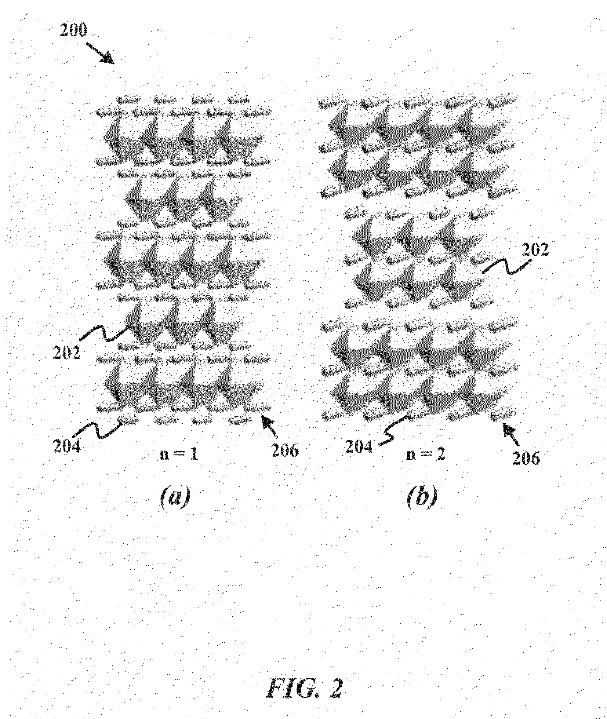
An anode in a Direct Carbon Fuel Cell (DCFC) operating in a temperature range between 500 and 1200 degrees Celsius is provided. The anode material has high catalytic activity and selectivity for carbon oxidation, sufficient oxygen non-stoichiometry, rapid oxygen chemical diffusion, wide thermodynamic stability window to withstand reducing environment, sufficient electronic conductivity and tolerance to sulfur and CO2 environments. The anode has doped ruthenate compositions A1−xA′xRuO3, AB1−yRuyO3, or A1−xA′xB1−yRuyO3. A and A′ may be divalent, trivalent, or tetravalent cation, and B is a multivalent cation. A is among lanthanide series elements La, Ce, Pr, Nd, Sm, Eu, Gd, Dy, Er or Yb, and dopant A′ is from Group IIA, IIIB, or IVB elements. The doped ruthenates can also be a (AB1−yRuyO3) structure or an ordered Ruddlesden-Popper series ((A1−xAx′)n+1(B1−yRuy)nO3n+1) structure where n=1 or 2. The dopant B is among Group IVB, VB, VIB, VIII, IB, and IIB elements.

Description

CROSS-REFERENCE TO RELATED APPLICATIONS[0001]This application is cross-referenced to and claims the benefit from U.S. Provisional Patent Application 60 / 852,335 filed Oct. 16, 2006, which is hereby incorporated by reference.FIELD OF THE INVENTION[0002]The invention relates to fuel cells, and, more particularly, cermet anodes for solid oxide fuel cells or a direct carbon fuel cells.BACKGROUND[0003]In applications for direct carbon fuel cells (DCFC), suitable materials for catalytic anodes remain a difficult problem when considering the commercialization of these technologies. The anodes in these fuel cells are subject to harsh environments that cause degradation in the anode, thus limiting optimum operational output. It has been an ongoing effort to create anode materials that can withstand not only extreme temperatures, but also steep gradients both in chemical and electrical potentials, severely reducing atmospheres, possible coking and sulfur poisoning, and carbon at unit activity ...

Claims


Application Information

Patent Timeline
IPC IPC(8): C01G55/00C01F17/00C01G31/00C01G45/00C01G53/00C01G23/00C01G25/00C01G37/00C01G41/00C01G49/00C01G51/00
CPCC01G55/002C01P2002/77C01P2002/78C01P2006/40H01M4/90Y02E60/50H01M8/1233H01M2004/8684H01M2008/1293Y02E60/525H01M4/9025
Inventor GUR, TURGUT M.
Owner DIRECT CARBON TECH
Learn More