
Multiple-tool machine for combined cutting of slabs of hard material

a multi-tool machine and cutting technology, applied in the field of hard material processing, can solve the problems of reducing the throughput of the apparatus, affecting the safety of operators, and difficulty in using the apparatus, and achieve the effect of high safety and throughpu

Inactive Publication Date: 2008-05-15
SIMEC SPA
View PDF11 Cites 59 Cited by
  • Summary
  • Abstract
  • Description
  • Claims
  • Application Information

AI Technical Summary

Benefits of technology

The present invention provides a machine for combined cutting of slabs of hard material that is highly efficient and relatively cost effective. The machine has two independently controllable cutting tools that can operate either at the same time or sequentially. It ensures a high throughput as compared with other available cutting apparatus. The machine can cut slabs into a plurality of shapes of any size and geometry, without needing manual handling of the semi-finished workpieces, while ensuring high levels of safety and throughput.

Problems solved by technology

Therefore, the required sequence of steps includes rather long setup and dead times, which reduce the throughput of the apparatus considerably.
Furthermore, any manual displacement of the strips may affect the safety of operators.
Nevertheless, these apparatus are not of easy use, in terms of both operation and cost, causing the use of waterjets to be generally limited to the cutting of edges or small portions of the slab.
Here again, the overall layout times are rather long, and two different cutting stations have to be provided, thereby affecting the cost effectiveness of the whole process.
While this solution eliminates the steps of manually preparing the strips to be cross-cut, simultaneous and independent control of the two slide-mounted tools are not enabled, therefore, the disk and the nozzle cannot be used at the same time.
One drawback of this solution is that the two tools are moved on common guide and cannot be used at the same time or simultaneous use thereof is greatly restricted, resulting in a reduced throughput of the entire apparatus.
Furthermore, the waterjet tool is only movable along three axes wherefore, after blade cutting, the beam has to be repositioned for alignment of the tool nozzle with the blade cut, with a disadvantageous increase of dead times.

Method used


Image

  • Multiple-tool machine for combined cutting of slabs of hard material
  • Multiple-tool machine for combined cutting of slabs of hard material
  • Multiple-tool machine for combined cutting of slabs of hard material

Examples


Embodiment Construction

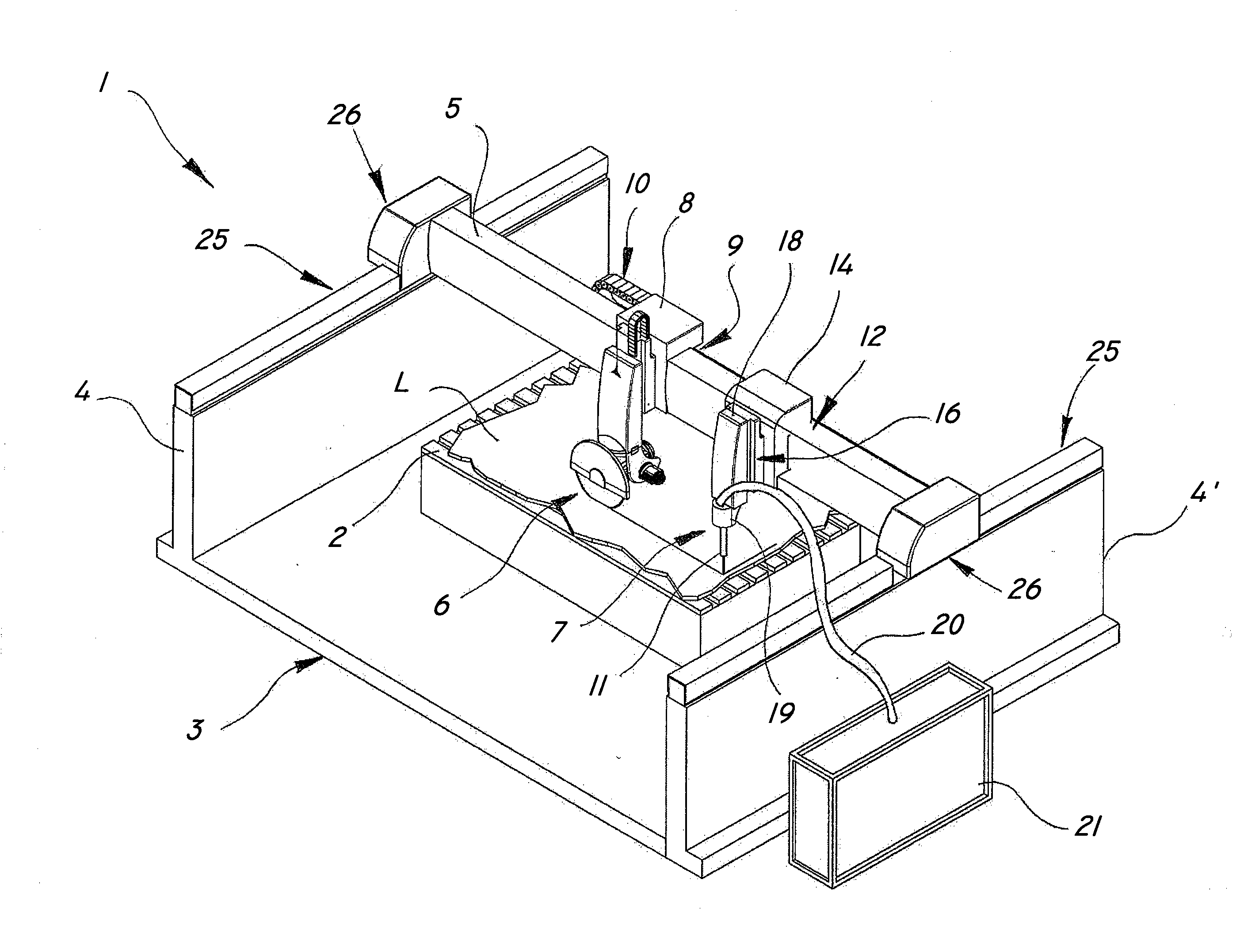
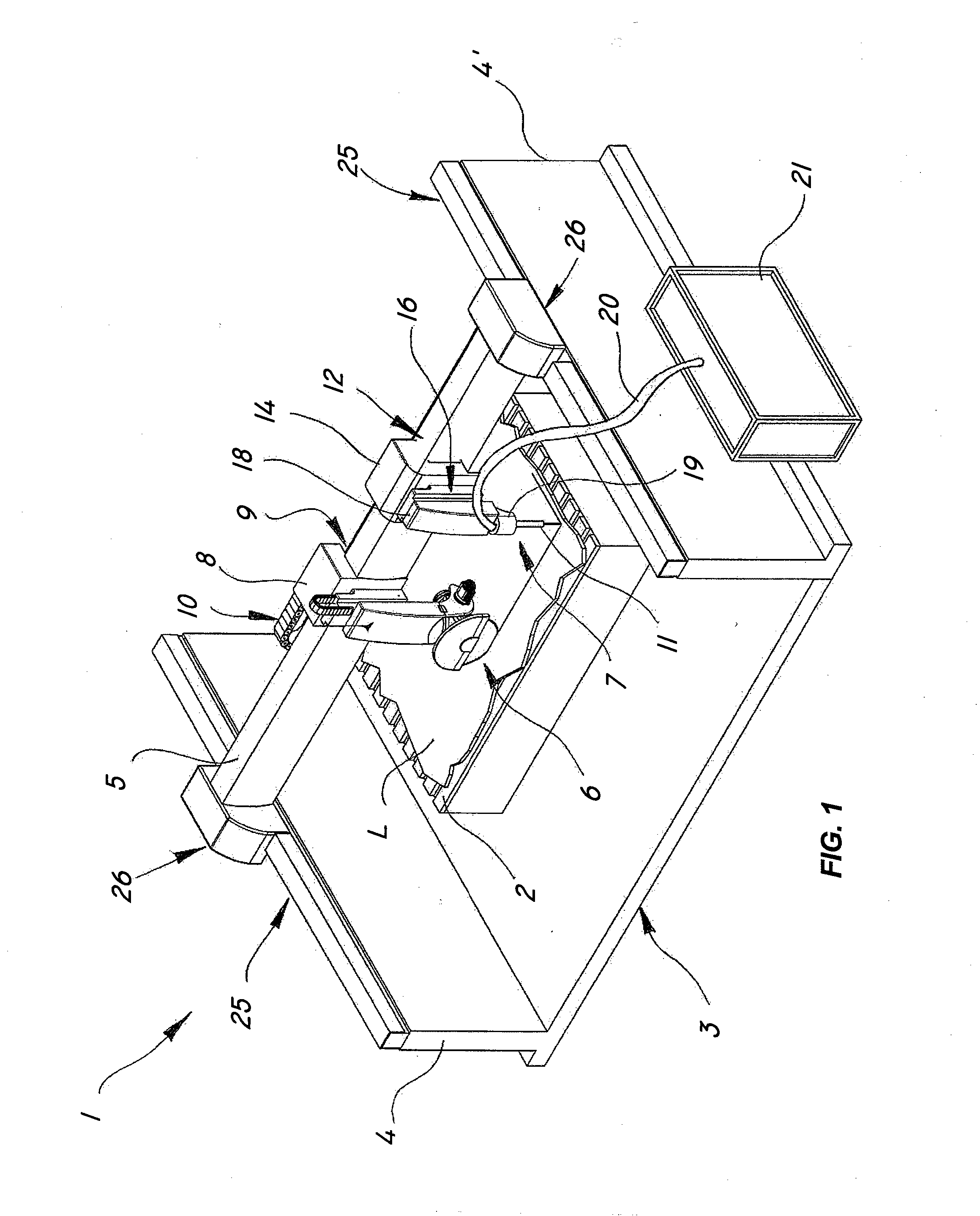
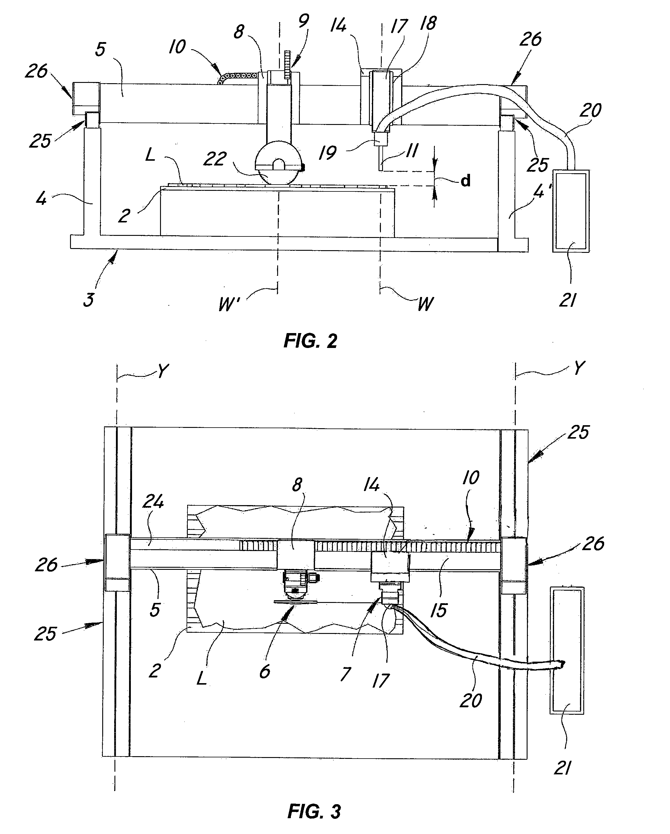
[0035]Referring to the figures, a machine according to the invention, generally designated by numeral 1, may be used for cutting slabs of hard material, such as marble, granite, metal, wood or the like, into a plurality of shapes of different sizes and geometries.

[0036]As shown more particularly in FIG. 1, a machine for the combined cutting of slabs comprises a substantially horizontal, fixed or adjustable support surface 2 for receiving a slab L to be cut; a load-bearing frame 3 with a pair of vertical posts 4, 4′; a substantially horizontal longitudinal beam 5, overlying the support surface 2; a first disk blade cutting tool 6 for making cuts of predetermined lengths on the slab L; and a second cutting tool 7 with a nozzle 11 for high-pressure waterjet cutting, which is designed to complete the cuts at the end areas and / or for finishing purposes.

[0037]The first tool 6 is mounted to a first slide 8 moving along a first guide 9 associated to beam 5, a first motion imparting device 1...


PUM

PropertyMeasurementUnit
lengthaaaaaaaaaa
lengthaaaaaaaaaa
thicknessaaaaaaaaaa

Abstract

The present invention relates to processing of hard materials, and more particularly relates to a multiple-tool machine for the combined cutting of slabs of hard materials such as stone, marble, granite, concrete, wood, metal, glass and the like. One embodiment of the present invention includes a support surface for receiving a slab; a load-bearing frame with a longitudinal beam extending over the support surface; a first disk blade cutting tool mounted on a first slide and movable along a first guide connected to the beam; a first motion imparting device for moving the first slide; a second cutting tool with a nozzle for high-pressure waterjet cutting, which is mounted in sliding relationship to a second guide coupled to the beam; and a second motion imparting device, other than the first motion imparting device, for translating the second cutting tool independently of the first cutting tool.

Description

FIELD OF THE INVENTION[0001]The present invention relates to the processing of hard materials. More particularly, the present invention relates to a multiple-tool machine for cutting slabs of hard materials, such as stone, marble, granite, concrete, wood, metal, glass and the like.BACKGROUND OF THE INVENTION[0002]Various types of apparatus are known in the art for cutting slabs of hard material, such as stone, marble, granite, wood and metal materials, into a plurality of plates not necessarily of the same shape and size.[0003]Generally, these apparatus include a work surface for receiving the slab to be cut, above which a rotary cutting tool, such as a disk, is translated.[0004]Usually, a cutting disk machine first provides longitudinal cuts to form a plurality of strips. Then, the strips are separated, by hand or by sliding in special spacing grids, for later crosscutting.[0005]This step is required especially when manufacturing tiles of different lengths to prevent the tool that ...

Claims


Application Information

Patent Timeline
Patent Type & Authority Applications(United States)
IPC IPC(8): B26F3/00B23D45/00
CPCB26F1/3813B28D1/043B28D1/003B26F3/004Y10T83/364Y10T83/7693
Inventor STANGHERLIN, AMPELIO
Owner SIMEC SPA
Learn More