
Mechanical stress improvement process

a stress improvement and process technology, applied in the field of mechanical stress improvement process, can solve the problems of stress corrosion cracking in stainless steal piping, crack propagation in weld metal, and cracks that have not been fully eliminated in bwr plants, so as to prevent the potential occurrence of primary water stress corrosion cracking

Active Publication Date: 2008-05-15
NUVISION ENG INC
View PDF5 Cites 18 Cited by
  • Summary
  • Abstract
  • Description
  • Claims
  • Application Information

AI Technical Summary

Benefits of technology

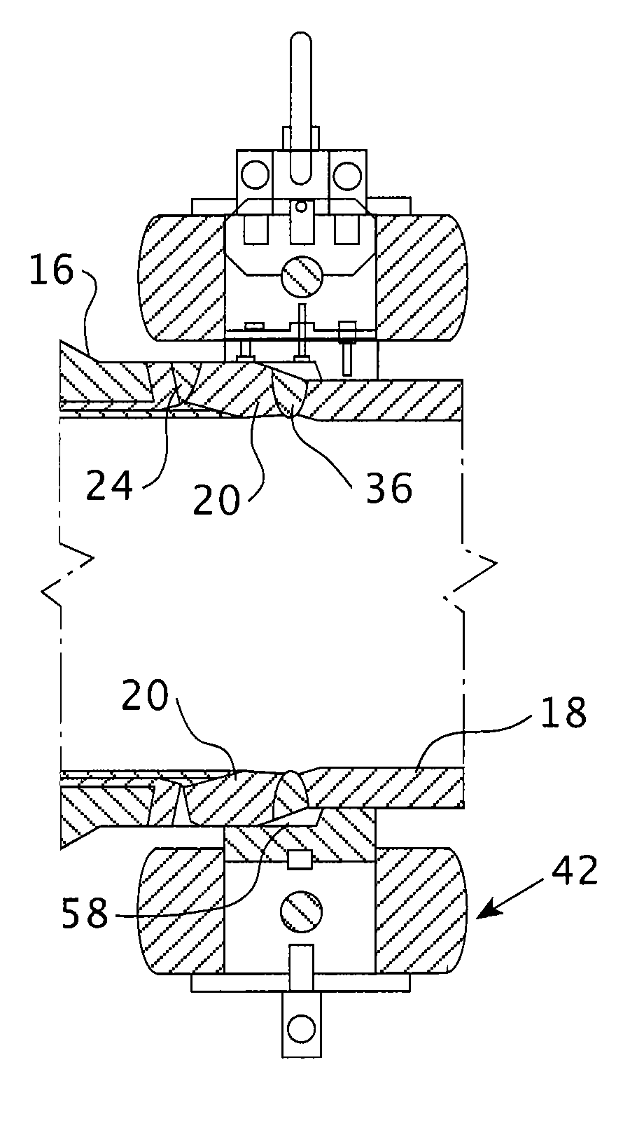
[0018]In one preferred embodiment the radial load applied is sufficient to obtain a permanent reduction in the outside diameter at a midplane where the load is applied in a range of about 0.2% to about 3.0% and preferably 0.6% to about 2.5%. The resulting compressive stresses are maintained from the inside until approximately 50 percent of the weld thickness, where the compressive stresses gradually change to tensile stresses, reaching the maximum level on the nozzle external surface; an area not susceptible to primary water stress corrosion cracking. The replacement of tensile stresses as provided herein, in the inner surface of the high nickel-chromium alloy welds between the low alloy nozzles and the austenitic stainless steel transition rings or safe-ends of the pressurized water reactor pressure vessel inlet and outlet nozzles and in pressurizer surge, spray, safety and relief nozzles, will mitigate and prevent the potential occurrence of primary water stress corrosion cracking in the nozzle end welds.

Problems solved by technology

These tensile stresses tend to enhance stress corrosion cracking in the weld region and the resulting crack propagation in the weld metal and in the heat-affected zone of such piping.
Stress corrosion cracking in stainless steal piping has been a serious drawback in boiling water reactor (BWR) plants in the United States and elsewhere in the world.
However, the occurrence of cracks have not been fully eliminated in the BWR plants.
The geometry of the nozzles and the short lengths of the thicker safe-ends do not readily lend themselves to the mechanical stress improvement process taught by either U.S. Pat. Nos. 4,683,014 and 4,612,071 for relieving the stresses on the nozzle to safe-end weld.
However, the process would have a high cost and radiation exposure and require an extended outage time.
This repair process will also have a high cost and radiation exposure and requires an extended outage time.
It is evident however, that any such induced compression would not stop the propagation of existing cracks that extend beyond the depth of the compressive layer.

Method used


Image

  • Mechanical stress improvement process
  • Mechanical stress improvement process
  • Mechanical stress improvement process

Examples


Embodiment Construction

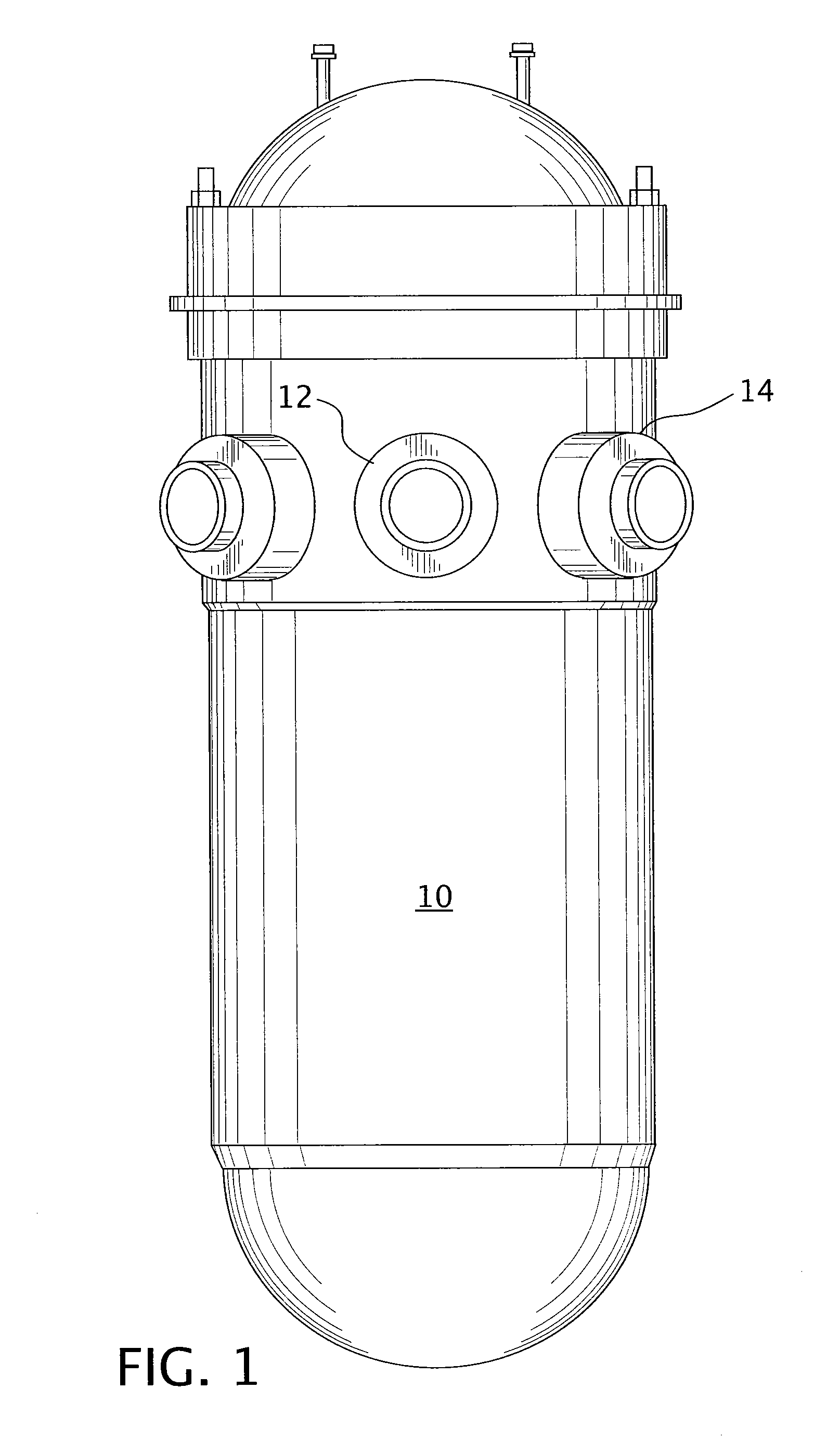
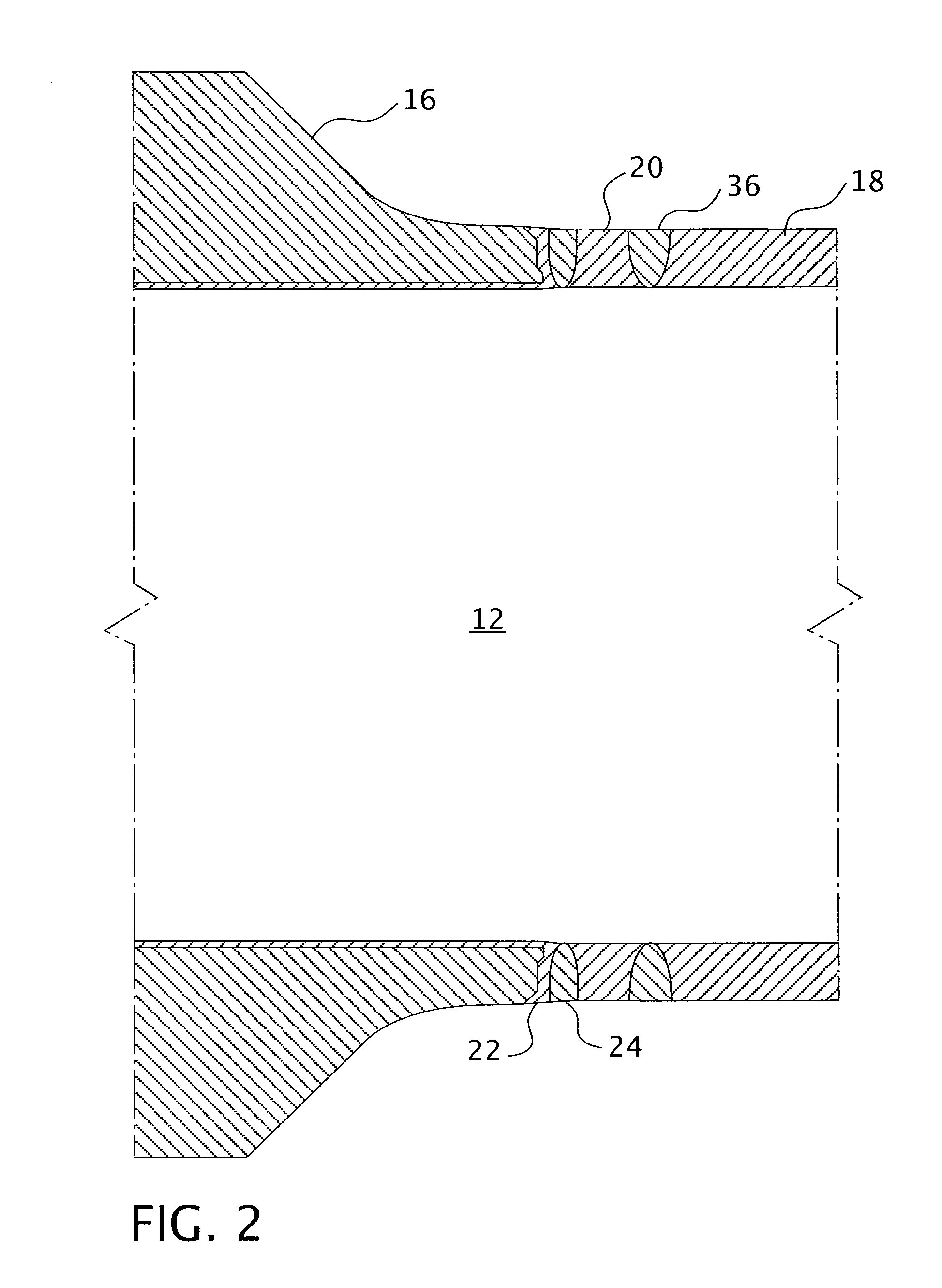
[0027]Pressurized water reactor nuclear steam supply system nozzles in the nuclear reactor pressure vessel upper shell course and in the pressurizer vessel upper and lower heads are normally manufactured with quenched and tempered low alloy steel forgings. Prior to the ASME code required post-weld heat treatment, the nozzle end is buttered with a weld deposit of high nickel-chromium coated electrodes or bare wire (commercially known respectively as Inconel 182 or 82). The minimum thickness of the buttering once machined is typically 0.125″ (0.3175 centimeters).

[0028]After post-weld heat treatment of the pressure vessel component and the machining of the buttered nozzle end to obtain a suitable bevel, the buttered nozzle end is normally welded to an austenitic stainless steel transition piece normally referred to as the nozzle safe-end. The nozzle safe-ends are welded to the reactor vessel and pressurizer nozzles by the pressure vessel manufacturer after post-weld heat treatment, but...


PUM

PropertyMeasurementUnit
Fractionaaaaaaaaaa
Fractionaaaaaaaaaa
Fractionaaaaaaaaaa

Abstract

A process for reducing residual tensile stresses in high nickel-chromium alloy nozzle safe-end welds of pressurized water reactor nuclear pressure vessels such as are found at the reactor vessel inlet and outlet nozzles and the pressurizes surge, spray, safety and relief nozzles. The process involves the application of radial compression on the outside surface of the nozzle's safe-end and / or connecting coolant piping, to reduce the outside diameter at the mid-point of the piping element to which the load is applied to between about 0.2% and about 3%. The radially compressive load applied by this process is imparted using a mechanical device that can be employed at the vessel manufacturer's facility or at a nuclear power plant after welding of the nozzle safe-end to the coolant piping or before either after plant commissioning of operation.

Description

BACKGROUND OF THE INVENTION[0001]1. Field of the Invention[0002]This invention relates generally to a process for removing the residual tensile welding stresses in the inner layer of a weld metal and heat affected zone that joins two dissimilar metals and more particularly for removing tensile residual stresses in a circumferential weld that joins a pressurized water reactor pressure vessel nozzle and a safe-end that are butt-welded to each other end to end.[0003]2. Description of the Prior Art[0004]When piping is butt-welded together by means of a circumferential weld, significant residual tensile welding stresses are produced in the weld metal and in the heat-affected zone of the piping. These tensile stresses tend to enhance stress corrosion cracking in the weld region and the resulting crack propagation in the weld metal and in the heat-affected zone of such piping.[0005]Stress corrosion cracking in stainless steal piping has been a serious drawback in boiling water reactor (BWR...

Claims


Application Information

Patent Timeline
IPC IPC(8): B21D3/00
CPCC21D1/30C21D9/50C21D9/08C21D6/004
Inventor BADLANI, MANUBELEY, BRIAN SCOTTDAMICO, THOMAS A.
Owner NUVISION ENG INC
Learn More