Eureka AIR delivers breakthrough ideas for toughest innovation challenges, trusted by R&D personnel around the world.

Vehicle System Having Regenerative Brake Control

a technology of regenerative brakes and braking systems, which is applied in the direction of braking systems, analogue processes for specific applications, instruments, etc., can solve the problems of wheel slippage, loss of directional control and possible greater stopping distance, and excessive slippage between the wheel and the road surfa

Active Publication Date: 2008-05-01
KELSEY HAYES CO
View PDF22 Cites 125 Cited by
  • Summary
  • Abstract
  • Description
  • Claims
  • Application Information

AI Technical Summary

Benefits of technology

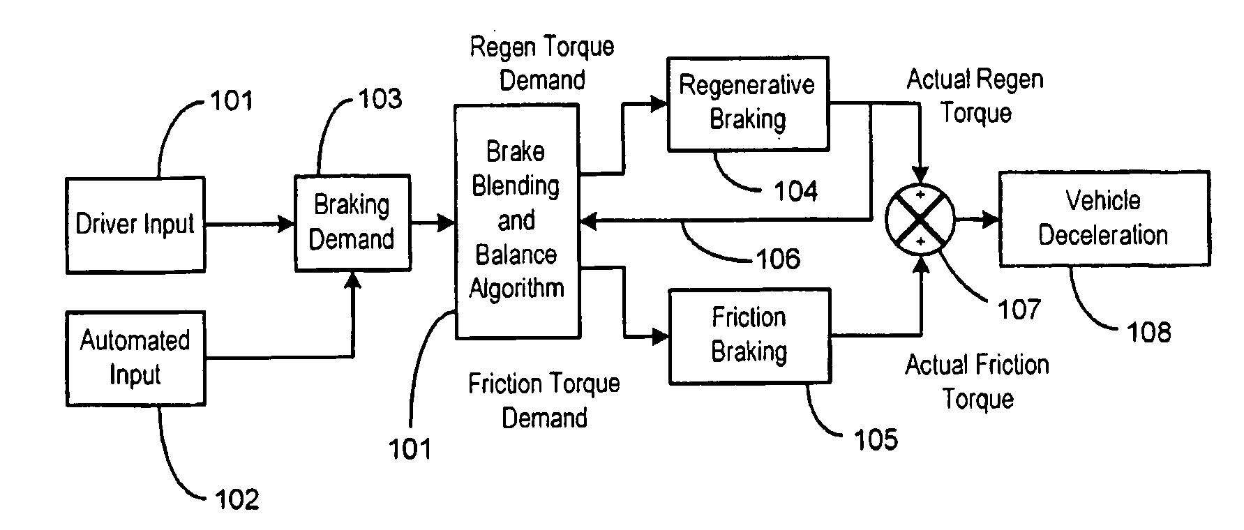
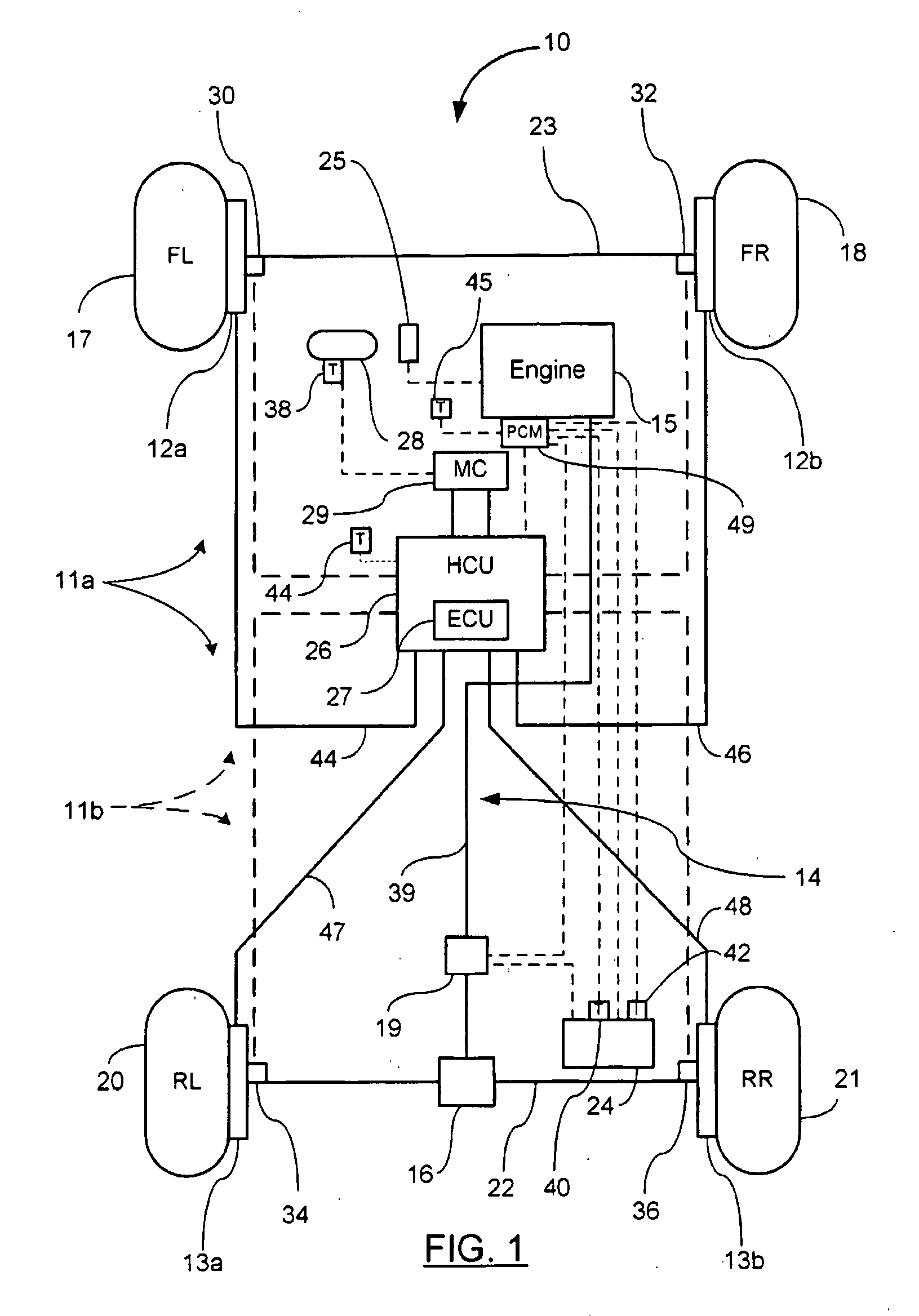
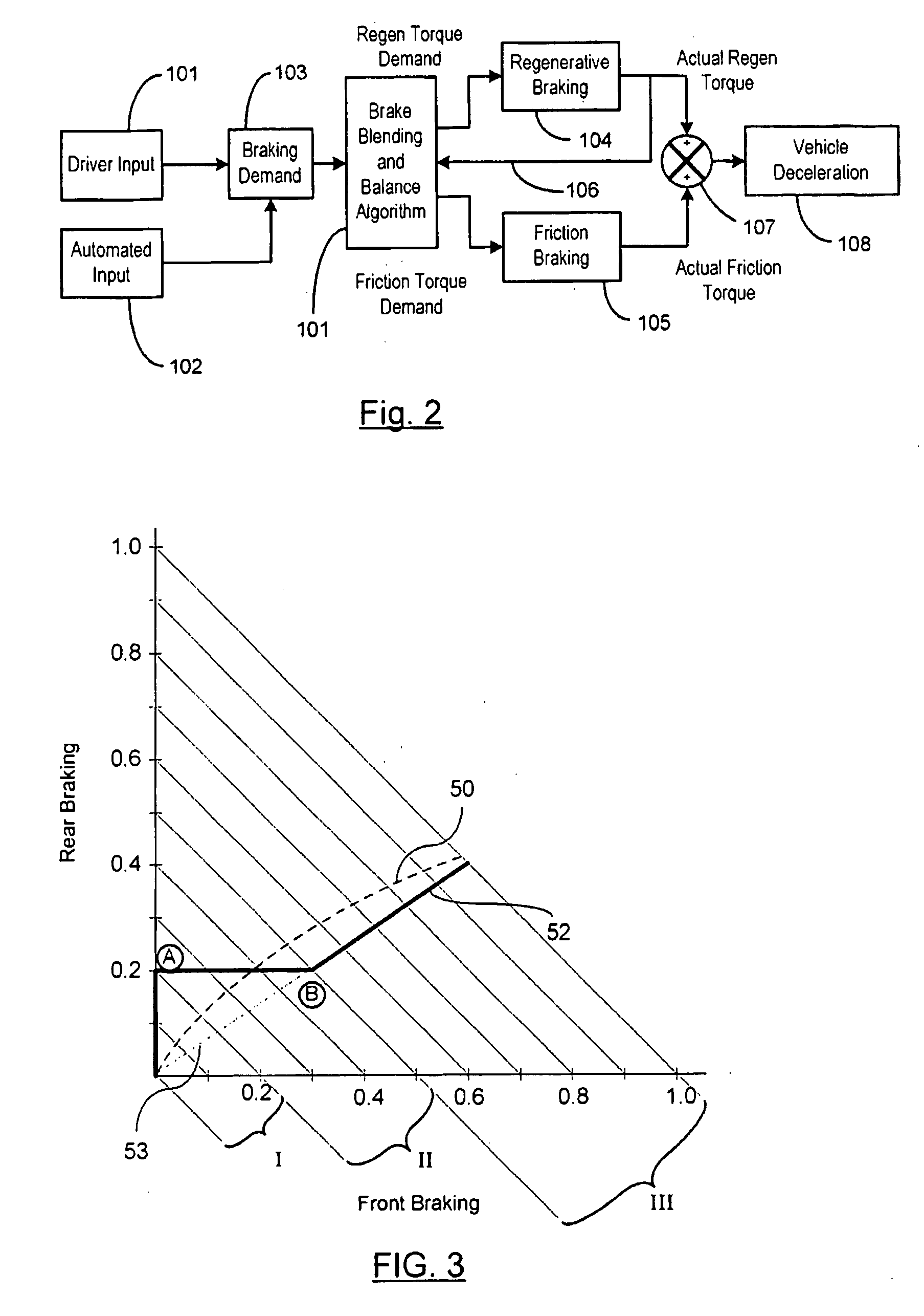
[0028]In one aspect of the present invention, a method is provided for controlling the braking of a vehicle that has a first set of friction brakes for applying a first apply brake force to a first set of wheels and a second set of friction brakes for applying a second brake apply force to a second set of wheels. A powertrain assembly is coupled to the second set of wheels. The powertrain assembly includes a regenerative braking unit capable of recapturing kinet...

Problems solved by technology

Under these conditions, a driver can easily apply excessive braking pressure thus causing one or more wheels to lock, resulting in excessive slippage between the wheel and road surface.
Wheel lock-up leads to loss of directional control and possible greater stopping distances.
Excessive torque applied to wheels during vehicle acceleration leads to wheel slippage and a loss of traction.
During vehicle motion such as cornering, dynamic forces are generated which can reduce vehicle stability.
The vehicle is also slowed as a result of the process of recapturing energy.

Method used


Image

  • Vehicle System Having Regenerative Brake Control
  • Vehicle System Having Regenerative Brake Control
  • Vehicle System Having Regenerative Brake Control

Examples


Embodiment Construction

[0029]In the following description of the invention, certain terminology will be used for the purpose of reference only, and are not intended to be limiting. Terms such as “upper”, “lower”, “above”, “below”, “rightward”, “leftward”, “clockwise”, and “counterclockwise” refer to directions in the drawings to which reference is made. Terms such as “inward” and “outward” refer to directions toward and away from, respectively, the geometric center of the component described. Terms such as “front”, “rear”, “side”, “right-hand”, “left-hand”, “top”, “bottom”, “horizontal”, and “vertical” describe the orientation of portions of the component within a consistent but arbitrary frame of reference which is made clear by reference to the text and the associated drawings describing the component under discussion. Such terminology will include the words specifically mentioned above, derivatives thereof, and words of similar meaning.

[0030]Throughout this specification and claims, the term “in fluid ...


PUM


Abstract

A method is provided for controlling the braking of a vehicle that has a first set of friction brakes for applying a first apply brake force to a first set of wheels and a second set of friction brakes for applying a second brake apply force to a second set of wheels. A powertrain assembly is coupled to the second set of wheels. The powertrain assembly includes a regenerative braking unit capable of recapturing kinetic energy from the second set of wheels. The vehicle is braked in a first phase of control using regenerative braking to brake the second set of wheels to achieve up to a first value of braking. The vehicle is braked in a second phase of control using the regenerative braking to maintain braking of the second set of wheels at the first value of braking force while selectively applying the first friction brakes to the first set of wheels up to a second value of braking.

Description

CROSS REFERENCE TO RELATED APPLICATIONS[0001]This application claims priority of U.S. Provisional Application Ser. No. 60 / 608,468 filed Sep. 9, 2004, and U.S. Provisional Patent Application Ser. No. 60 / 686,802 filed Jun. 1, 2005, the disclosures of which are incorporated by reference.STATEMENT REGARDING FEDERALLY SPONSORED RESEARCH[0002]Not Applicable.BACKGROUND OF THE INVENTION[0003]1. Field of the Invention[0004]This invention relates in general to vehicle braking systems, and in particular to a method of controlling a braking system having regenerative brake control.[0005]2. Background of the Invention[0006]Vehicular regenerative braking systems generally capture forward kinetic energy from braking events and use that recovered energy to accelerate the vehicle. By using energy recovered from braking, the energy efficiency of the vehicle is improved. Regenerative braking may be used on vehicles having hybrid or pure electric powertrain platforms. On many of these hybrid or pure el...

Claims


Application Information

Patent Timeline
IPC IPC(8): B60L7/22B60T13/58B60K6/48
CPCB60K6/48B60L7/18B60T13/586Y02T10/6221B60W10/08B60W10/184B60W20/00B60T2270/602Y02T10/62B60W20/13
Inventor LUBBERS, MARK D.
Owner KELSEY HAYES CO
Why Eureka
Eureka Blog
Learn More