Pressure sensor having improved arrangement of sensor chip for minimizing influence external vibrations
a technology of pressure sensor and sensor chip, which is applied in the field of pressure sensors, can solve the problems of pressure sensor b sensing error and pressure sensor sensing error, and achieve the effect of high accuracy of pressure sensor and minimized vibration on the pressure-receiving surfa
- Summary
- Abstract
- Description
- Claims
- Application Information
AI Technical Summary
Benefits of technology
Problems solved by technology
Method used
Image
Examples
first embodiment
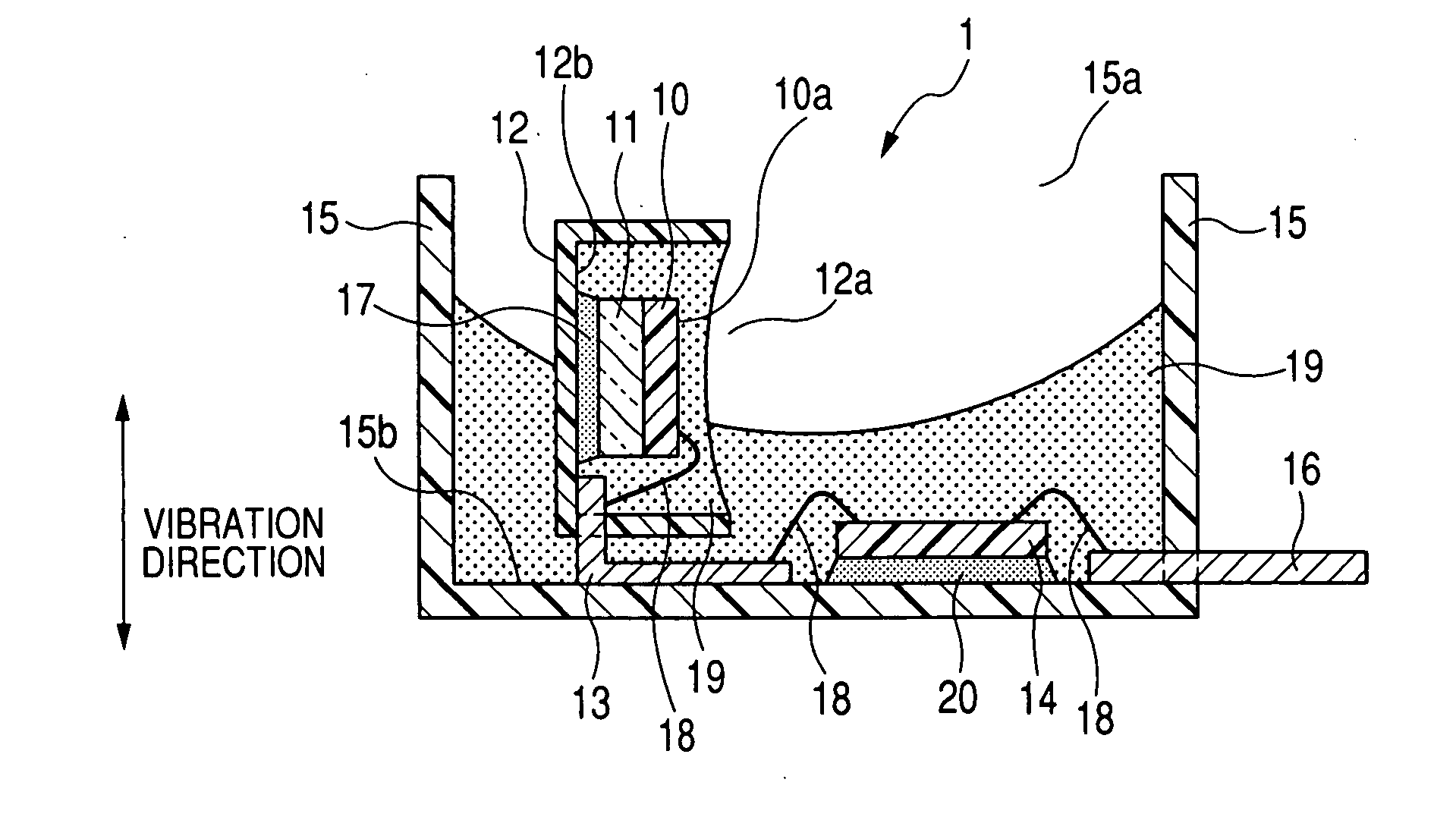
[0026]FIG. 1 shows the overall structure of a pressure sensor 1 according to the first embodiment of the invention. The pressure sensor 1 is designed to be installed in an interior space formed in a door of a vehicle to sense the air pressure change in the interior space caused by a collision against the door.
[0027]The interior space may be formed between an outer panel on the outside and a door trim on the inner side of the door. Otherwise, when there is further provided an inner trim between the outer panel and the door trim, the interior space may formed either between the outer panel and the inner trim or between the inner trim and the door trim.
[0028]As shown in FIG. 1, the pressure sensor 1 includes a sensor chip 10, a glass seat 11, a sub case 12, a plurality of terminals 13, a circuit chip 14, a main case 15, and a plurality of terminals 16.
[0029]The sensor chip 10 includes a diaphragm (not shown) for sensing pressure. The diaphragm has a bridge circuit formed therein and a ...
second embodiment
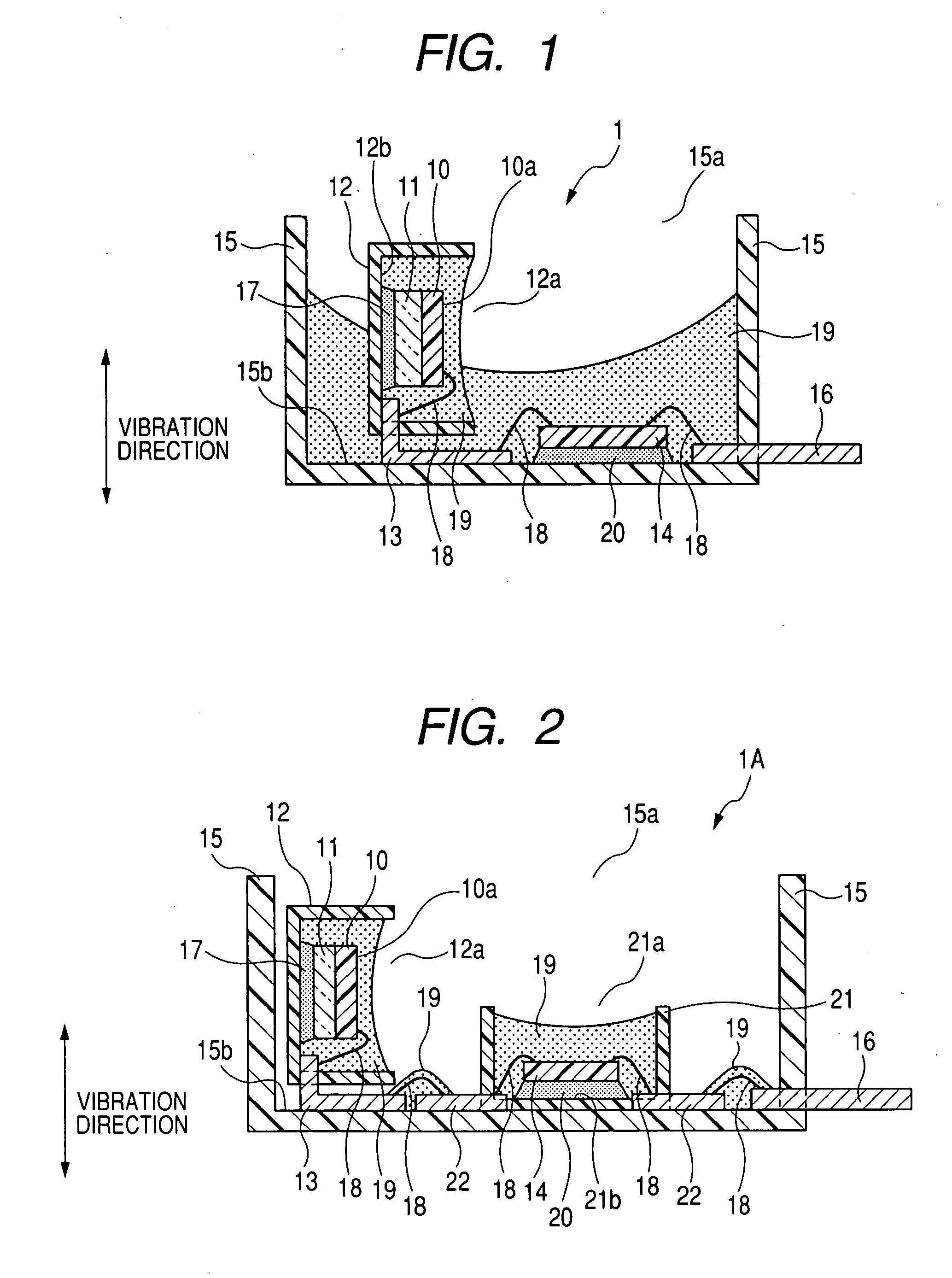
[0045]FIG. 2 shows the overall structure of a pressure sensor 1A according to the second embodiment of the invention. The structure of the pressure sensor 1A is similar to that of the pressure sensor 1 according to the first embodiment; accordingly, only the differences therebetween will be described.
[0046]In the pressure sensor 1, as described previously, the circuit chip 14 is directly mounted to the main case 15.
[0047]In comparison, as shown in FIG. 2, the pressure sensor 1A further includes a sub case 21 and a plurality of terminals 22.
[0048]The sub case 21 is made of resin and has the shape of a cup with an opening 21a and an inner end surface 21b. The sub case 21 is disposed on the inner end surface 15b of the main case 15 so that the inner end surface 21b of the sub case 21 is parallel to the inner end surface 15b of the main case 15. The circuit chip 14 is received in the sub case 21 and fixed to the inner end surface 21b by the adhesive 20.
[0049]The terminals 22 are provide...
third embodiment
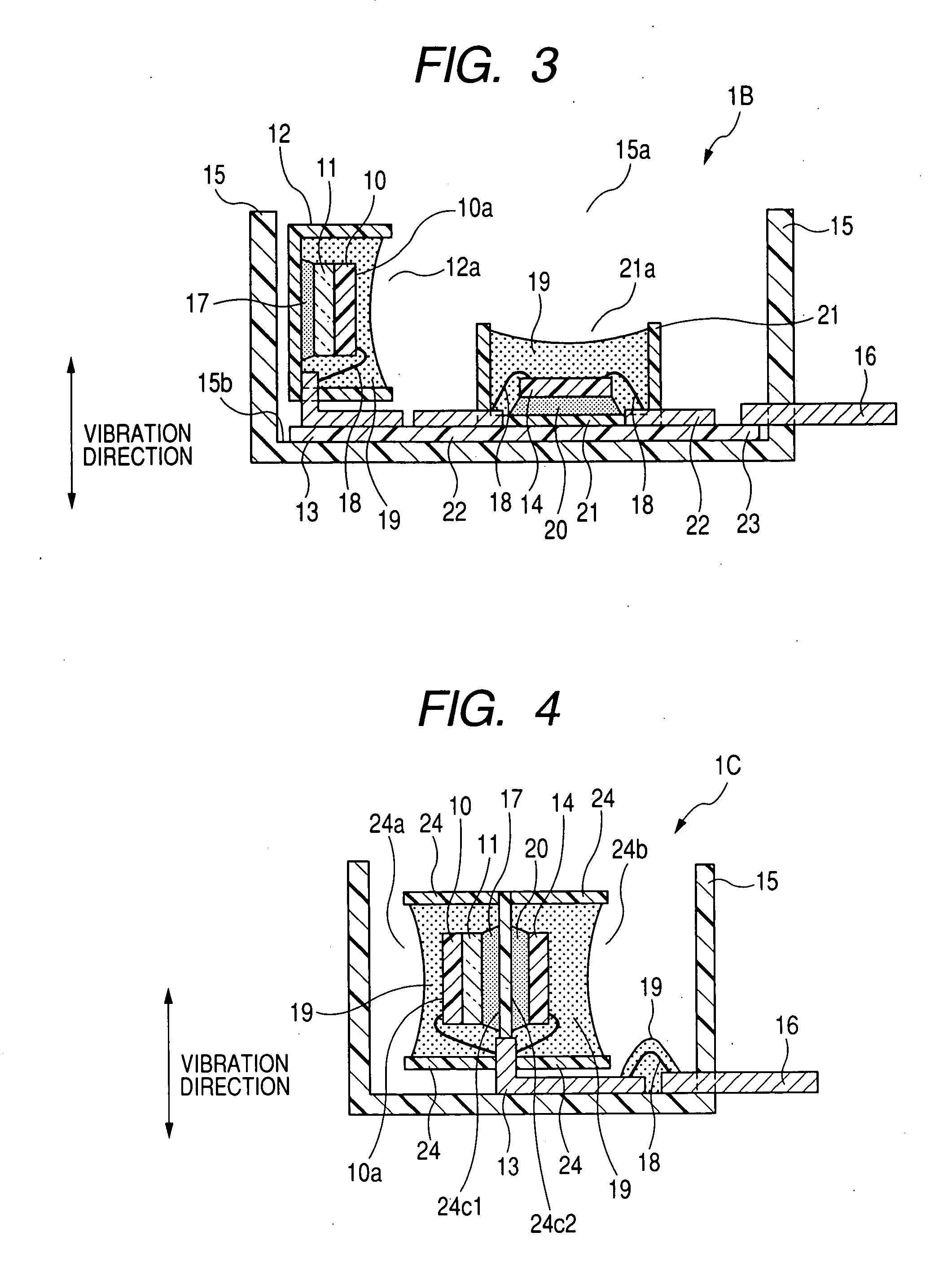
[0053]FIG. 3 shows the overall structure of a pressure sensor 1B according to the third embodiment of the invention. The structure of the pressure sensor 1B is similar to that of the pressure sensor 1A according to the second embodiment; accordingly, only the differences therebetween will be described.
[0054]In the pressure sensor 1A, as described previously, the terminals 22 are electrically connected to the terminals 13 or 16 by the wire bonding 18.
[0055]In comparison, as shown in FIG. 3, the pressure sensor 1B further includes a printed wiring board 23 that electrically connects the terminals 22 to the terminals 13 or 16.
[0056]The printed wiring board 23 is made up of a glass epoxy board or flexible board, on which a conductive pattern (not shown) is formed by wiring patterns and contact pads. The printed wiring board 23 is fixed to the inner end surface 15b of the main case 15 by screws (not shown) or an adhesive (not shown). The terminals 13, 22, and 16 are joined to the corresp...
PUM
 Abstract
Description
Claims
Application Information
 - R&D
- Intellectual Property
- Life Sciences
- Materials
- Tech Scout
- Unparalleled Data Quality
- Higher Quality Content
- 60% Fewer Hallucinations
Browse by: Latest US Patents, China's latest patents, Technical Efficacy Thesaurus, Application Domain, Technology Topic, Popular Technical Reports.
© 2025 PatSnap. All rights reserved.Legal|Privacy policy|Modern Slavery Act Transparency Statement|Sitemap|About US| Contact US: help@patsnap.com


