
Computing system capable of parallelizing the operation graphics processing units (GPUs) supported on a CPU/GPU fusion-architecture chip and one or more external graphics cards, employing a software-implemented multi-mode parallel graphics rendering subsystem

a graphics processing unit and parallel processing technology, applied in computing, digital computers, instruments, etc., can solve problems such as slowing down the working rate of graphics systems

Inactive Publication Date: 2008-04-24
LUCID INFORMATION TECH +1
View PDF99 Cites 40 Cited by
  • Summary
  • Abstract
  • Description
  • Claims
  • Application Information

AI Technical Summary

Benefits of technology

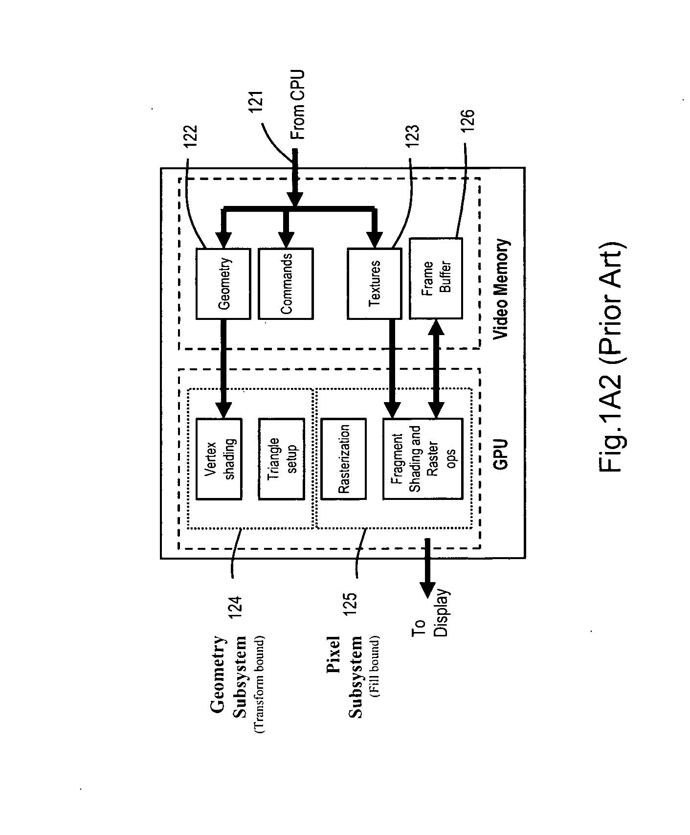
[0034] As illustrated in FIG. 3B, the Object Division (Sort-Last) Method of Parallel Graphics Rendering decomposes the 3D scene (i.e. rendered database) and distributes graphics display list data and commands associated with a portion of the scene to the particular graphics pipeline (i.e. rendering unit), and recombines the partially rendered pixel frames, during recomposition. The geometric database is therefore shared among GPUs, reducing the load on the geometry buffer, the geometry subsystem, and even to some extent, the pixel subsystem. The main concern is how to divide the data in order to keep load balance. An exemplary multiple-GPU platform of FIG. 3B for supporting the object-division method is shown in FIG. 3A. The platform requires complex and costly pixel compositing hardware which prevents its current application in a modern PC-based computer architecture.
[0035] Today, real-time graphics applications, such as advanced video games, are more demanding than ever, utilizing massive textures, abundance of polygons, high depth-complexity, anti-aliasing, multi-pass rendering, etc., with such robustness growing exponentially over time.

Problems solved by technology

This, in turn, causes both computational and buffer contention challenges which slow down the working rate of the graphics system.

Method used


Image

  • Computing system capable of parallelizing the operation graphics processing units (GPUs) supported on a CPU/GPU fusion-architecture chip and one or more external graphics cards, employing a software-implemented multi-mode parallel graphics rendering subsystem
  • Computing system capable of parallelizing the operation graphics processing units (GPUs) supported on a CPU/GPU fusion-architecture chip and one or more external graphics cards, employing a software-implemented multi-mode parallel graphics rendering subsystem
  • Computing system capable of parallelizing the operation graphics processing units (GPUs) supported on a CPU/GPU fusion-architecture chip and one or more external graphics cards, employing a software-implemented multi-mode parallel graphics rendering subsystem

Examples


example

Consideration of A General Scene

[0377] Denote the time for drawing n polygons and p pixels as Render(n,p), and allow P to be equal to the time taken to draw one pixel. Here the drawing time is assumed to be constant for all pixels (which may be a good approximation, but is not perfectly accurate). Also, it is assumed that the Render function, which is linearly dependent on p (the number of pixels actually drawn), is independent of the number of non-drawings that were calculated. This means that if the system has drawn a big polygon that covers the entire screen surface first, then for any additional n polygons: Render(n,p)=p×P. Render⁡(n,p)=∑i=1∞⁢ ⁢P×{x|LayerDepth⁡(x)=i}×E⁡(i)(5)

[0378] The screen space of a general scene is divided into sub-spaces based on the layer-depth of each pixel. This leads to some meaningful figures.

[0379] For example, suppose a game engine generates a scene, wherein most of the screen (90%) has a depth of four layers (the scenery) and a small part is cov...


PUM


Abstract

A computing system capable of parallelizing the operation of multiple graphics processing units (GPUs) supported on external graphics cards, employing a multi-mode parallel graphics rendering subsystem. The computing system includes (i) CPU memory space for storing one or more graphics-based applications, (ii) a CPU / GPU fusion-architecture chip including one or more CPUs, one or more GPUs, a memory controller for controlling the CPU memory space, and an interconnect network, and (iii) an external graphics cards supporting multiple GPUs and being connected to the CPU / GPU fusion-architecture chip by way of a data communication interface. The computing system also includes (iv) an external graphics card supporting multiple GPUs and being connected to the CPU / GPU fusion-architecture chip by way of a data communication interface, (v) the multi-mode parallel graphics rendering subsystem supporting multiple modes of parallel operation, (vi) a plurality of graphic processing pipelines (GPPLs) implemented using the GPUs, and (vii) an automatic mode control module. During the run-time of the graphics-based application, the automatic mode control module automatically controls the mode of parallel operation of the multi-mode parallel graphics rendering subsystem so that the GPUs are driven in a parallelized manner.

Description

CROSS-REFERENCE TO RELATED CASES [0001] The present application is a Continuation of U.S. application Ser. No. 11 / 897,536 filed Aug. 30, 2007; which is a Continuation-in-Part (CIP) of the following Applications: U.S. application Ser. No. 11 / 789,039 filed Apr. 23, 2007; U.S. application Ser. No. 11 / 655,735 filed Jan. 18, 2007, which is based on Provisional Application Ser. No. 60 / 759,608 filed Jan. 18, 2006; U.S. application Ser. No. 11 / 648,160 filed Dec. 31, 2006; U.S. application Ser. No. 11 / 386,454 filed Mar. 22, 2006; U.S. application Ser. No. 11 / 340,402 filed Jan. 25, 2006, which is based on Provisional Application No. 60 / 647,146 filed Jan. 25, 2005; U.S. application Ser. No. 10 / 579,682 filed May 17, 2006, which is a National Stage Entry of International Application No. PCT / IL2004 / 001069 filed Nov. 19, 2004, which is based on Provisional Application Ser. No. 60 / 523,084 filed Nov. 19, 2003; each said patent application being commonly owned by Lucid Information Technology, Ltd., a...

Claims


Application Information

Patent Timeline
IPC IPC(8): G06F15/80
CPCG06F9/5066
Inventor BAKALASH, REUVENLEVIATHAN, YANIV
Owner LUCID INFORMATION TECH
Learn More