
Alloy and method for producing magnetic refrigeration material particles using same

a technology of magnetic refrigeration material and alloy, which is applied in the direction of heat treatment apparatus, magnetic bodies, furnaces, etc., can solve the problems of poor practical utility, unconsidered uniformity of the properties of the particles obtained by fabricating into the spherical particles, and the ribbon-like magnetic refrigeration material

Active Publication Date: 2008-04-03
KK TOSHIBA
View PDF6 Cites 36 Cited by
  • Summary
  • Abstract
  • Description
  • Claims
  • Application Information

AI Technical Summary

Benefits of technology

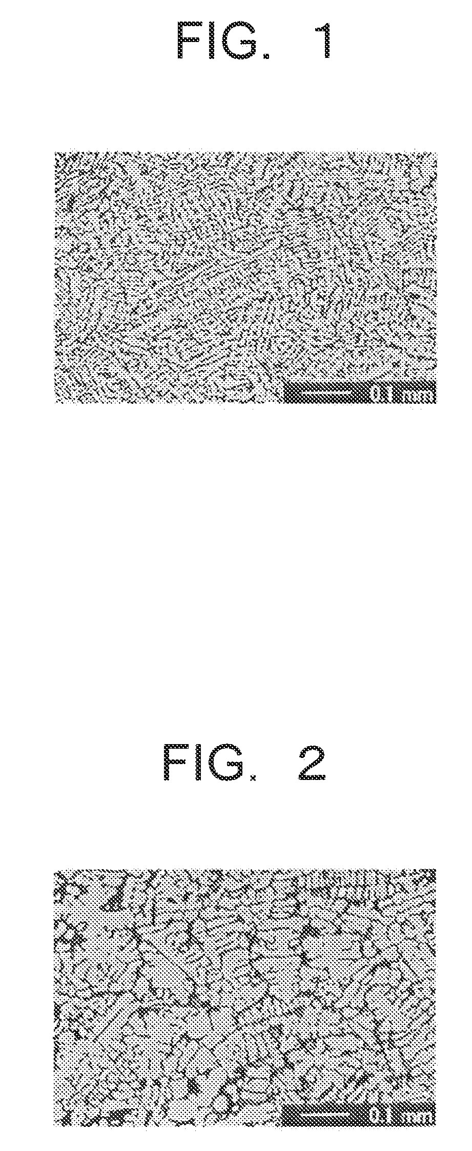
[0017]An alloy according to an aspect of the present invention contains La in a range of 4 atomic % to 15 atomic %, Fe in a range of 60 atomic % to 93 atomic %, Si in a range of 3.5 atomic % to 23.5 atomic % and at least one element M selected from B and Ti in a range of 0.5 atomic % to 1.5 atomic %, and includes a main phase containing Fe as a main component element and Si, and a subphase containing La as a main component element and Si, the main phase having a bcc crystal structure and an average grain diameter of 20 μm or less.
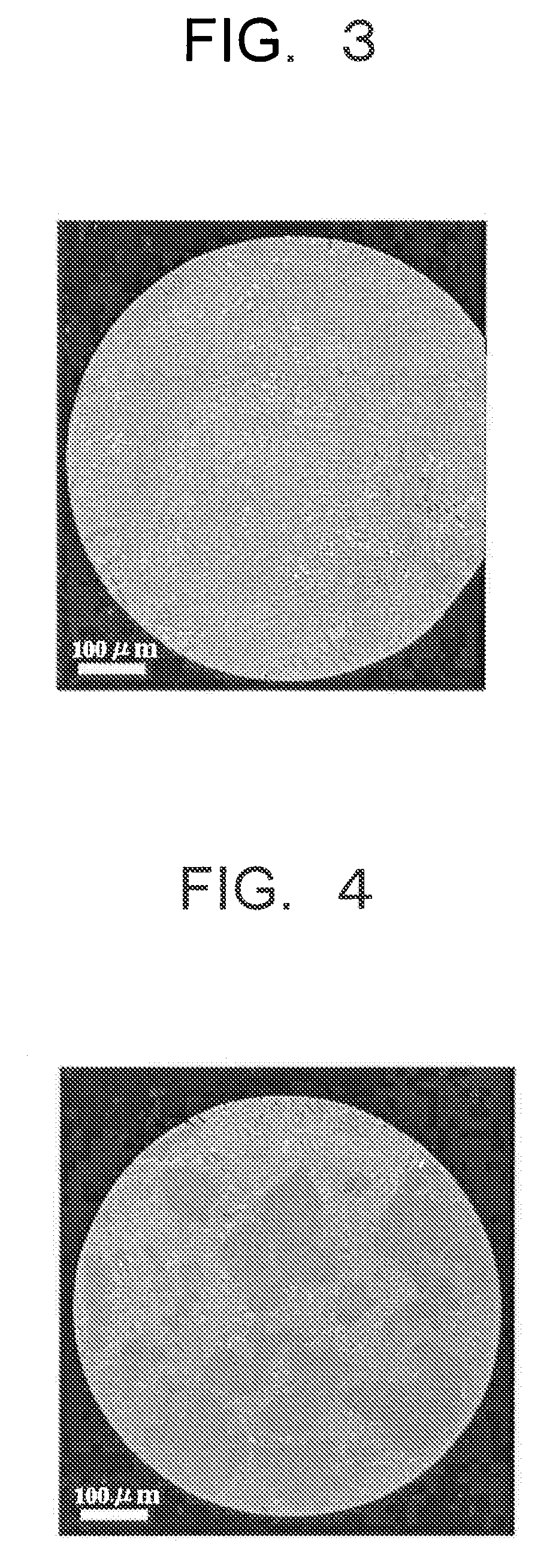
[0018]A method for producing magnetic refrigeration material particles according to another aspect of the present invention includes, melting partially with plasma the alloy material according to the aspect of the present invention; separating the melted alloy into small pieces in a molten state; spheroidizing the melted alloy separated into the small pieces by the surface tension in an atmosphere; solidifying the spheroidized small pieces in an atmosphere; and performing a heat treatment of the solidified small pieces.

Problems solved by technology

Thus, the production process of the La(Fe, Si)13 phase using a bulk material by applying an ordinary melting method has drawbacks that it is essential to perform the heat treatment at a relatively high temperature for (long term of) several days to several months.
As described above, since the magnetic refrigeration material is desirably used by fabricating into the spherical particles, the ribbon-like magnetic refrigeration material has a drawback that it has poor practical utility.
But, fabricability into spherical particles and uniformity of the properties among the particles obtained by fabricating into the spherical particles are not taken into consideration.
The former method has a disadvantage that the filling factor of the magnetic refrigeration material lowers depending on the pulverized shapes because the mother alloy undergone the heat treatment is pulverized into small pieces.
There is a problem that cracks (cracking) are produced within the small pieces by a stress applied when pulverizing to make them brittle, and the small pieces are finely divided during the magnetic refrigeration operation to disturb the operation.
However, in a case where the mother alloy produced on the basis of a conventional material composition is applied to the rotary electrode process, the composition ratio of the spherical particles becomes variable because of the coarse two-phase separated state of the mother alloy, and it becomes a cause of degrading the properties of the magnetic refrigeration material particles.
Thus, a sufficient refrigerating effect cannot be obtained by a thermal cycle test according to the AMR method.

Method used


Image

  • Alloy and method for producing magnetic refrigeration material particles using same
  • Alloy and method for producing magnetic refrigeration material particles using same
  • Alloy and method for producing magnetic refrigeration material particles using same

Examples


examples 7 to 10

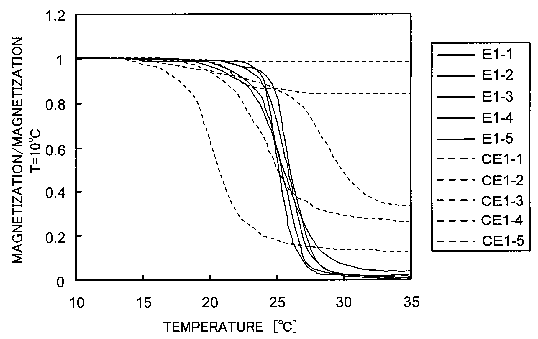
[0077]Cylindrical mother alloys were produced in the same manner as in Example 1 excepting that the compositions shown in Table 2 were applied. The individual mother alloys of Examples 7 to 10 were confirmed to have the Fe alloy phases having the bcc crystal structure as the main phase. The mother alloys were used to produce spherical particles in the same manner as in Example 1, and the heat treatment was performed under the nearly same conditions (about 980 to 1080° C.) as in Example 1. The magnitudes ΔT were measured with the ambient temperatures of the individual spherical particles changed. Maximum values (ΔTmax) of ΔT are shown in Table 2.

TABLE 2Alloy composition (atomic %)LaCePrFeCoMnNiAlSiBΔTmaxE76.450.7—76.147.43———8.350.931.7CE96.450.7—76.147.43———9.28—0.5E86.94—0.274.279.3—0.93—7.430.931.4CE106.94—0.274.279.3—1.86—7.43—0.4E97.15——74.297.890.930.93—7.431.381.3CE117.15——74.287.890.930.93—8.82—0.6E107.15——74.297.89——9.29—1.381.3CE127.15——74.279.29——9.29——0.3E = Example,CE = ...


PUM

PropertyMeasurementUnit
grain diameteraaaaaaaaaa
lengthaaaaaaaaaa
diameteraaaaaaaaaa

Abstract

An alloy is used for production of magnetic refrigeration material particles. The alloy contains La in a range of 4 to 15 atomic %, Fe in a range of 60 to 93 atomic %, Si in a range of 3.5 to 23.5 atomic % and at lease one element M selected from B and Ti in a range of 0.5 to 1.5 atomic %. The alloy includes a main phase containing Fe as a main component element and Si, and a subphase containing La as a main component element and Si. The main phase has a bcc crystal structure and an average grain diameter of 20 μm or less.

Description

CROSS-REFERENCE TO RELATED APPLICATIONS[0001]This application is based upon and claims the benefit of priority from the prior Japanese Patent Application No. 2006-268339 filed on Sep. 29, 2006; the entire contents of which are incorporated herein by reference.BACKGROUND OF THE INVENTION[0002]1. Field of the Invention[0003]The present invention relates to an alloy and a method for producing magnetic refrigeration material particles using the same.[0004]2. Description of the Related Art[0005]When a magnetic field applied to a certain type of magnetic substance is changed in an adiabatic state, its temperature is changed. This phenomenon is called a magnetocaloric effect. Physically, the degree of freedom of magnetic spins of the magnetic substance is changed by the magnetic field, and the entropy of a magnetic spin system (electron system responsible for (attributed to) magnetism) is changed as a result. With the entropy change, an instantaneous energy transfer occurs between the elec...

Claims


Application Information

Patent Timeline
Patent Type & Authority Applications(United States)
IPC IPC(8): C22C38/02B22F9/10C21D9/00
CPCB22F9/10C21D9/0068H01F1/015C22C38/02C22C38/005
Inventor SAITO, AKIKOKOBAYASHI, TADAHIKOTSUJI, HIDEYUKI
Owner KK TOSHIBA
Learn More