
Magnetic core using amorphous soft magnetic alloy

a soft magnetic alloy and magnetic core technology, applied in the field of magnetic cores, can solve the problems of low electrical resistivity, large relative permeability of magnetic cores, and limitation of the number of lines permeable through magnetic cores, so as to suppress vibration and noise, and increase the loss of cores.

Active Publication Date: 2008-04-03
ALPS ALPINE CO LTD
View PDF7 Cites 40 Cited by
  • Summary
  • Abstract
  • Description
  • Claims
  • Application Information

AI Technical Summary

Benefits of technology

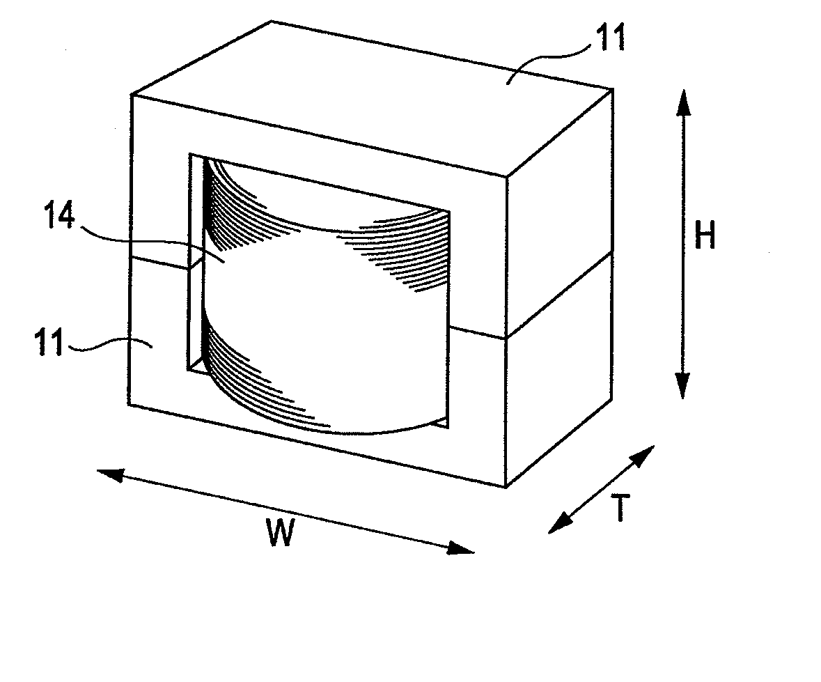
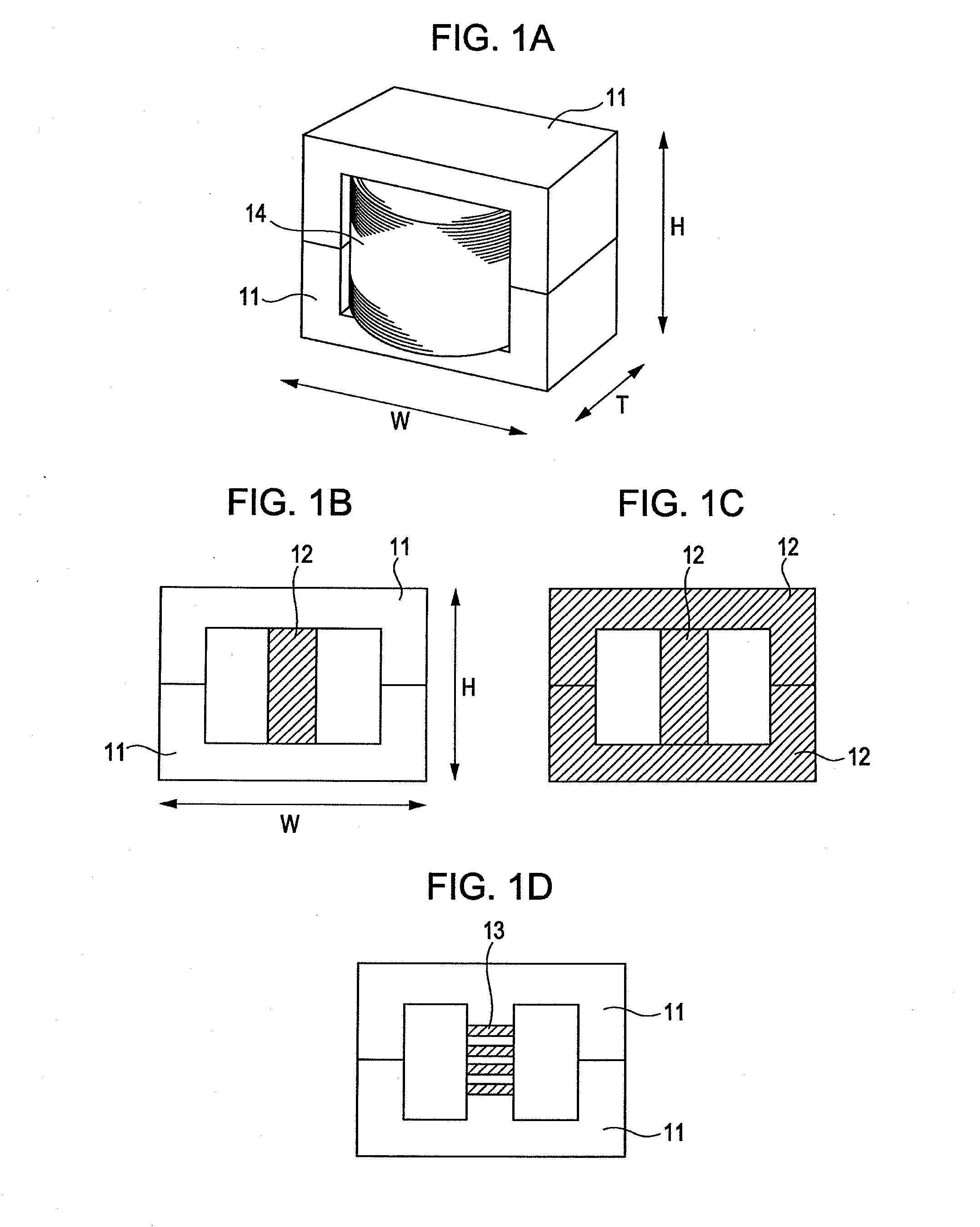
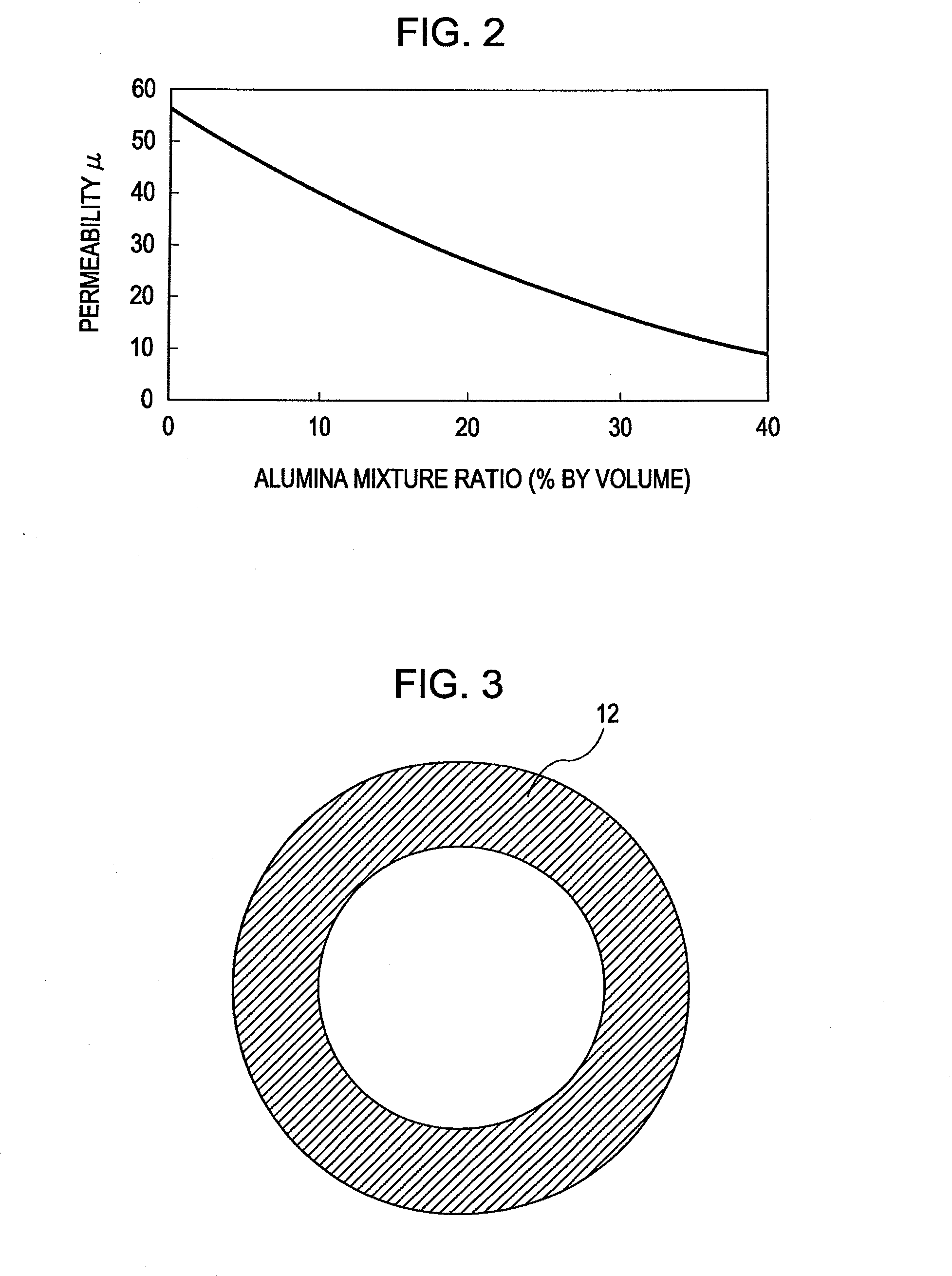
[0014] Looking in a microscopic scale, the magnetic core of the compressed compact is in a state where the nonmagnetic inorganic matter is interposed between adjacent portions of the amorphous soft magnetic iron alloy. In such a state, the amorphous soft magnetic iron alloy is not completely continuous and is partly cut by the nonmagnetic inorganic matter. This means that the amorphous soft magnetic iron alloy has magnetic micro-gaps filled by the nonmagnetic inorganic matter. The micro-gaps act to generate demagnetizing fields in a direction to reduce a magnetic field within the magnetic core, thus reducing apparent permeability. By controlling a mixture ratio of the nonmagnetic inorganic matter, the permeability can be reduced to a level suitable for a coil which is used in an application requiring supply of a large current flow. Further, in the magnetic core of the compressed compact, since the permeability is reduced with the presence of the micro-gaps which are smaller than sizes of magnetic particles, instead of a large gap used in the known magnetic core, magnetic flux is prevented from leaking through the gaps, and an increase of the core loss including the iron loss and the copper loss can be suppressed. In addition, the magnetic core of the compressed compact has heat resistance and can suppress vibrations and noise caused by the vibrations.
[0018] The producing method according to the disclosed embodiment can provide the magnetic core of the compressed compact which has permeability at such a low level as allowing use in an application requiring supply of a large current flow, which can suppress an increase of the core loss including the iron loss and the copper loss, which has heat resistance, and which can suppress vibrations and noise caused by the vibrations.

Problems solved by technology

The number of lines of magnetic force permeable through a magnetic core has a limitation.
Accordingly, a magnetic core made of such a core material having large relative permeability is not suitable for a choke coil used in a power supply of an electronic device in which a large current flows.
General soft magnetic iron alloys, such as a FeNi alloy, a Fe—Si alloy, and a Fe—Al—Si alloy, have relatively low electrical resistivity and therefore tend to generate a large eddy-current loss.
However, when a gap is formed in a magnetic path as in the related art, apparent permeability can be reduced, but magnetic flux leaks through the gap, thus resulting in an increase of a core loss including an iron loss and a copper loss.
In addition, noise is generated due to the vibrations.
In that application, a problem occurs in practical use in that noise is generated due to vibrations near the gap formed in the magnetic path.
In the structure (Patent Document 1) in which the gap is filled with, e.g., a nonmagnetic body to maintain sufficient strength in a portion around the gap, the man-hours needed in the manufacturing process are increased and the cost is pushed up.
Also, just simply filling the gap with, e.g., a nonmagnetic body is not a sufficient measure against the noise and a further improvement of the antinoise measure is required for practical use.
Another disadvantage is that the mixed material is susceptible to changes of resin components between before and after the annealing and to characteristic changes during a severe heat resistance test.
In other words, the mixed material has various problems when used as materials of cores for use in products which are required to have heat resistance under severe applications, such as a reactor in hybrid cars.

Method used


Image

  • Magnetic core using amorphous soft magnetic alloy
  • Magnetic core using amorphous soft magnetic alloy
  • Magnetic core using amorphous soft magnetic alloy

Examples


example 1

[0058] Amorphous soft magnetic iron alloy particles with an average particle size (D50) of 12 μm were produced by atomizing an amorphous soft magnetic alloy having a composition of Fe77.9Cr1P7.3C2.2B7.7Si3.9 with the water atomization method. Then, 53.6% by volume (72% by weight) of the thus-produced amorphous soft magnetic iron alloy particles were mixed with 35.0% by volume (25.7% by weight) of alumina particles, i.e., the nonmagnetic inorganic matter, with an average particle size (D50) of 6 μm to prepare a mixed material. At that time, 9.8% by volume (2.0% by weight) of a silicon resin (made by Shinetsu Chemical Co., Ltd. under the trade name of Silicon Resin ES1001N) was added as the binder, and 1.6% by volume (0.3% by weight) of lead stearate was added as the grease. Various kinds of mixed materials were prepared in a similar manner while changing the mixture ratio of the nonmagnetic inorganic matter. The actually used mixture ratios of the nonmagnetic inorganic matter are sho...


PUM

PropertyMeasurementUnit
Percent by volumeaaaaaaaaaa

Abstract

A magnetic core made of a mixed material including powder of an amorphous soft magnetic iron alloy and about 10% by volume or more of nonmagnetic inorganic powder, the amorphous soft magnetic iron alloy being expressed by the following composition: Fe100-a-b-x-y-z-w-tCOaNibMxPyCzBwSit wherein M is one or two or more elements selected from among Cr, Mo, W, V, Nb, Ta, Ti, Zr, Hf, Pt, Pd and Au, and a, b, x, y, z, w and t represent composition ratios satisfying 0 atom %≦x≦3 atom %, 2 atom %≦y≦15 atom %, 0 atom %≦z≦8 atom %, 1 atom %≦w≦12 atom %, 0.5 atom %≦t≦8 atom %, 0 atom %≦a≦20 atom %, 0 atom %≦b≦5 atom %, and 70 atom %≦(100-a-b-x-y-z-w-t)≦80 atom %.

Description

CLAIM OF PRIORITY [0001] This application claims benefit of the Japanese Patent Application No. 2006-266216 filed on Sep. 29, 2006 and No. 2007-178930 filed on Jul. 6, 2007, which are hereby incorporated by reference. BACKGROUND [0002] 1. Field of the Invention [0003] The present invention relates to a magnetic core of a compressed compact used in a coil for a power supply circuit and also relates to a method of producing the magnetic core. [0004] 2. Description of the Related Art [0005] Choke coils are used in step-up and step-down circuits and smoothing circuits of electronic devices. The choke coil accumulates, as magnetic energy, a magnetic field generated by a current. The number of lines of magnetic force permeable through a magnetic core has a limitation. Upon reaching the limitation, even when a current supplied to the choke coil is increased, the number of lines of magnetic force passing through the magnetic core is not increased over the limitation and the accumulated magn...

Claims


Application Information

Patent Timeline
IPC IPC(8): H01F1/153
CPCC22C33/0207C22C33/0228H01F1/15366C22C2202/02H01F1/15308C22C2200/02
Inventor NAITO, YUTAKAAOKI, KAZUOABE, MASATOMIKANEKO, KAZUYA
Owner ALPS ALPINE CO LTD
Learn More