
Mn-Zn based ferrite member

a ferrite member and zn-based technology, applied in the field of zn-based ferrite members, can solve the problems of poor magnetic properties, large loss, insufficient direct current superposition properties, etc., and achieve excellent mass productivity, increase resistance, and low loss

Inactive Publication Date: 2007-10-30
TDK CORPARATION
View PDF12 Cites 0 Cited by
  • Summary
  • Abstract
  • Description
  • Claims
  • Application Information

AI Technical Summary

Benefits of technology

The solution provides a Mn—Zn based ferrite member with high withstand voltage, low loss, and excellent direct current superposition properties, outperforming Ni—Zn based ferrites, and enabling efficient production for small low-profile power coils and transformers.

Problems solved by technology

The former type permits downsizing but is large in loss and poor in magnetic properties, and has a problem such that the direct current superposition property is insufficient.
On the other hand, the latter type is small in loss, excellent in magnetic properties, and permits, for example, forming a coil having an excellent direct current superposition property; however, this type has a small core resistance, which necessitates combinational use of an insulating bobbin, and thereby makes downsizing of this type difficult.
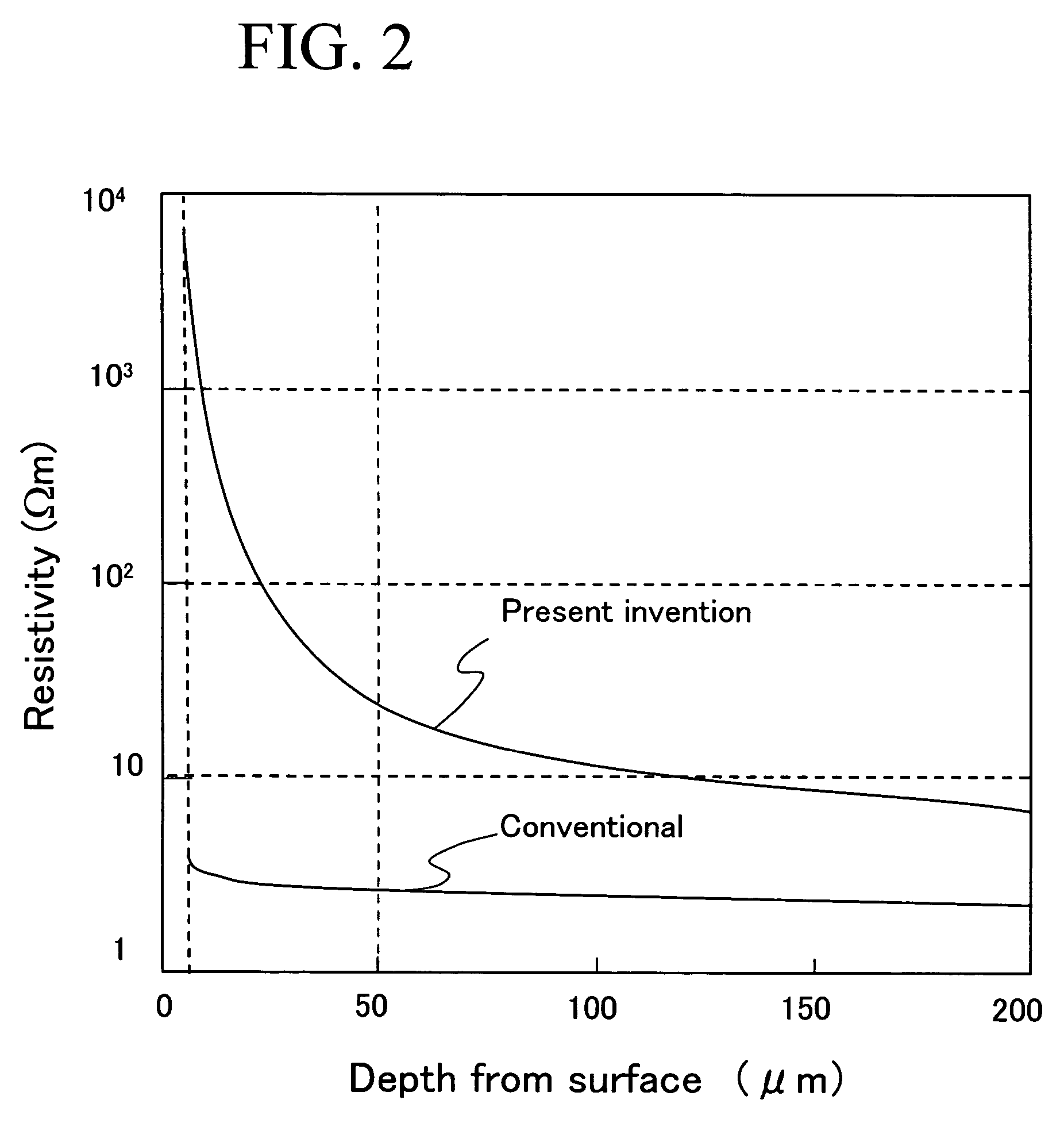
However, the Mn—Zn based ferrite member obtained in Patent Document 2 has a small surface layer resistance of the order of 1×10³ Ωm, accordingly the withstand voltage being hardly made sufficient.
The cause for the insufficient development of the surface resistance may be understood that the introduction of air decreases the temperature of the atmosphere in the course of the oxidation treatment, thus preventing the oxidation from proceeding sufficiently.
Although this method can give a sufficient withstand voltage, the iron-poor composition drastically increases the loss, and moreover, degrades the magnetic properties so as to be equivalent to those of Ni—Zn based ferrite.
These techniques each can decrease the core loss and can provide a high withstand voltage and high magnetic properties, but the step to form the coating film is cumbersome and these techniques are thereby poor in mass productivity.

Method used


Image

  • Mn-Zn based ferrite member
  • Mn-Zn based ferrite member
  • Mn-Zn based ferrite member

Examples


example 1

[0070]As the ferrite raw materials, a Fe2O3 powder: 54 mol %, a MnO powder: 39.5 mol % and a ZnO powder: 6.5 mol % were prepared and subjected to wet mixing, and then the mixture was calcined at 850° C. for 3 hours. Next, the calcined substance was milled and the powder thus obtained was added with a binder. The mixture thus obtained was subjected to granulation and compacting to obtain a compacted body.

[0071]The obtained compacted body was sintered. The sintering was carried out under the conditions that the temperature was increased up to 1300° C. in a nitrogen atmosphere, then the oxygen partial pressure was regulated at 3% over a period of 5 hours, and thereafter the temperature was decreased in a nitrogen atmosphere. The density, saturation magnetic flux density Bs, and permeability μ of the thus obtained sintered body were measured to be 4.93 g / cm3 (relative density: 97.3%), 540 mT and 2400, respectively.

[0072]Next, φ15 mm×10 mm cylindrical sintered bodies were subjected to an...

example 2

[0095]Samples were prepared in the same manner as in Example 1 except that the annealing conditions were such that 600° C.×1 hour, 700° C.×1 hour, 700° C.×2 hours and 700° C.×8 hours, and the withstand voltage and ρ5 values thereof were measured. The results thus obtained are shown in Table 3 and FIG. 7. As can be seen from Table 3 and FIG. 7, when the extent of the oxidation based on the annealing treatment is increased, ρ5 is increased and the withstand voltage is improved. In particular, when ρ5 is made to be 1000 Ωm or more, a withstand voltage of 50 V or more can be obtained.

[0096]

TABLE 3Withstand voltageρ5Annealing conditions(V)(Ωm)No annealing1010600° C. × 1 hour20100700° C. × 1 hour30323700° C. × 2 hours601560700° C. × 8 hours905509

example 3

[0097]Samples were prepared in the same manner as in Example 1 except that the annealing conditions were such that 700° C.×4 hours, 800° C.×4 hours and 850° C.×2 hours, and the core loss (Pcv) values and the above described R50 and R200 values thereof were measured. The results thus obtained are shown in Table 4 and FIG. 8. When R50≦10×R200, the core loss (Pcv) can be made to be 600 kW / m3 or less.

[0098]

TABLE 4AnnealingR50R200Pcvconditions(kΩ)(kΩ)R50 / R200(kW / m3)No annealing3.423.391.01335700° C. × 4 hours6.153.421.80425800° C. × 4 hours35.63.879.20586850° C. × 2 hours1485.5926.481050


PUM

PropertyMeasurementUnit
areaaaaaaaaaaa
temperatureaaaaaaaaaa

Abstract

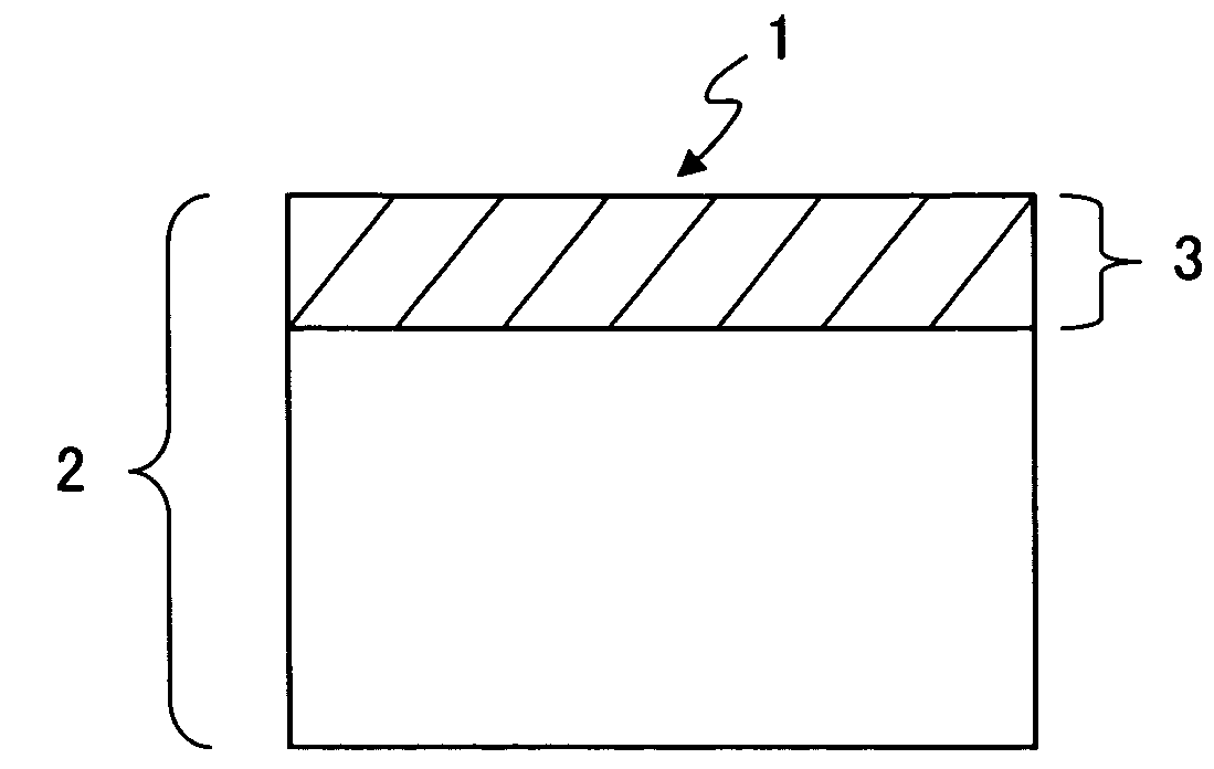
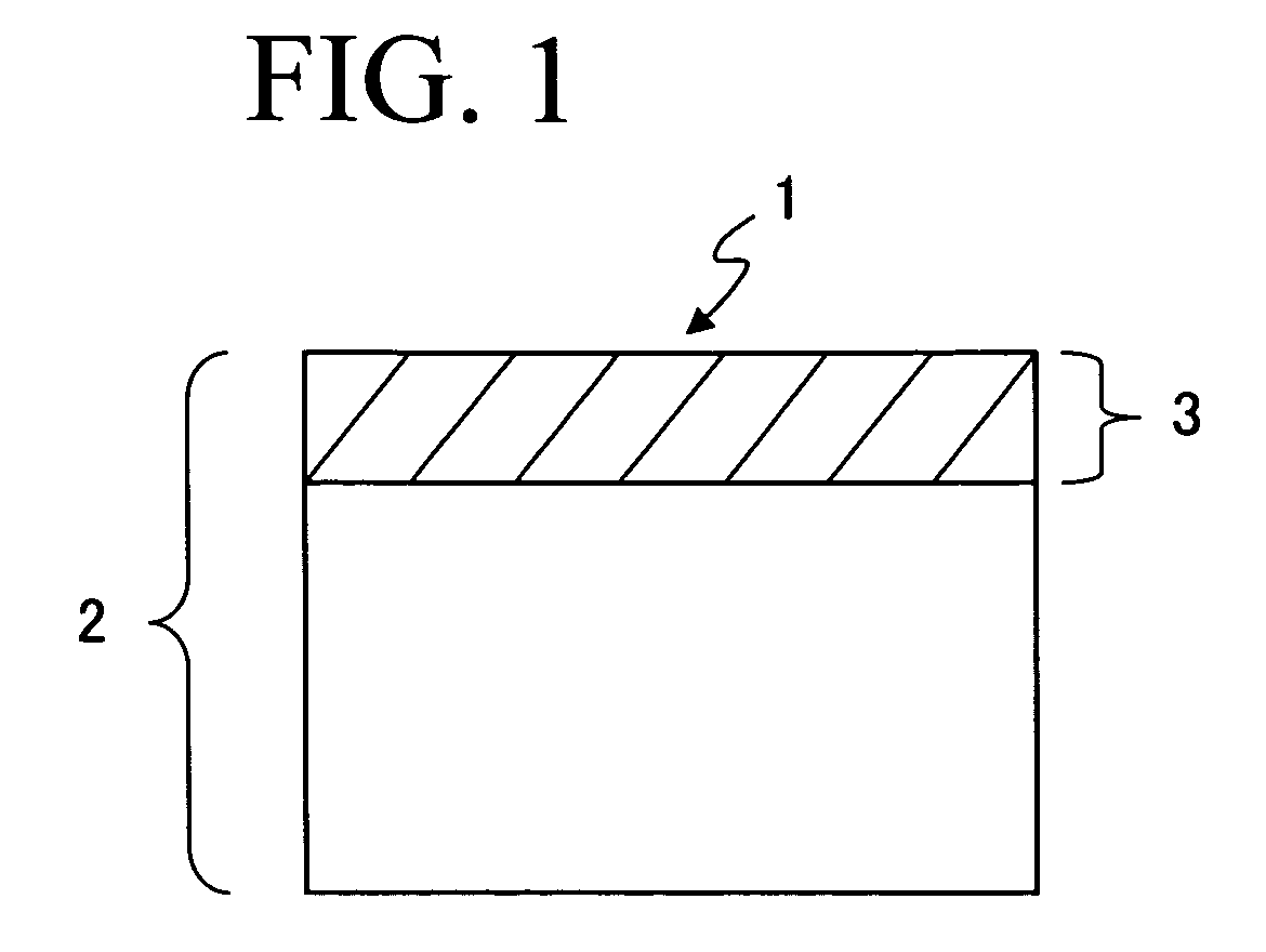
There is provided a Mn—Zn based ferrite member excellent in mass productivity, high in withstand voltage, low in loss and excellent in direct current superposition property. The Mn—Zn based ferrite member is provided with a surface layer portion having the properties that ρ5 defined in the specification satisfies the relation that ρ5≧103 Ωm and ρ50 defined in the specification satisfies the relation that ρ50≦102 Ωm.ρ5: (R0−R1)S / L5 (Ωm)ρ50: (R2−R3)S / L50 (Ωm)

Description

BACKGROUND OF THE INVENTION[0001]1. Field of the Invention[0002]The present invention relates to a Mn—Zn based ferrite member to be suitably used as a core in a coil and as a core in a transformer, in particular, a Mn—Zn based ferrite member to be suitably used as a core for a small low-profile power coil and as a core for a small low-profile power transformer each displaying a low loss, a high withstand electric voltage (hereinafter referred to as withstand voltage) and excellent magnetic properties, and having high mass productivity.[0003]2. Description of the Related Art[0004]As the cores for small low-profile power devices, there have hitherto been used cores formed by using Ni—Zn ferrite, directly winding wire therearound and forming terminal electrodes, or cores formed by combining an insulating bobbin and Mn—Zn based ferrite. The former type permits downsizing but is large in loss and poor in magnetic properties, and has a problem such that the direct current superposition pr...

Claims


Application Information

Patent Timeline
Patent Type & Authority Patents(United States)
IPC IPC(8): H01F7/02C04B35/38B32B15/00C01G49/00C04B35/26H01F1/00H01F1/34H01F41/02
CPCC01G49/0018C04B35/2658C04B35/62655C04B35/6303C04B35/64C22C29/12H01F1/344H01F41/0246C01G49/009Y10T428/12465C01P2006/42C04B2235/3208C04B2235/3212C04B2235/3232C04B2235/3239C04B2235/3244C04B2235/3251C04B2235/3256C04B2235/3262C04B2235/3263C04B2235/3284C04B2235/3286C04B2235/3287C04B2235/3293C04B2235/3294C04B2235/3298C04B2235/3418C04B2235/42C04B2235/656C04B2235/6567C04B2235/6584C04B2235/663C04B2235/77C04B2235/85C04B2235/96Y10T428/12792
Inventor KAJINO, TAKASHITAKAGAWA, KENYAMURASE, TAKUAOKI, TAKUYA
Owner TDK CORPARATION
Learn More