
System and Method for Software Debugging

Inactive Publication Date: 2008-03-27
ZINGHER ARTHUR R
View PDF3 Cites 61 Cited by
  • Summary
  • Abstract
  • Description
  • Claims
  • Application Information

AI Technical Summary

Benefits of technology

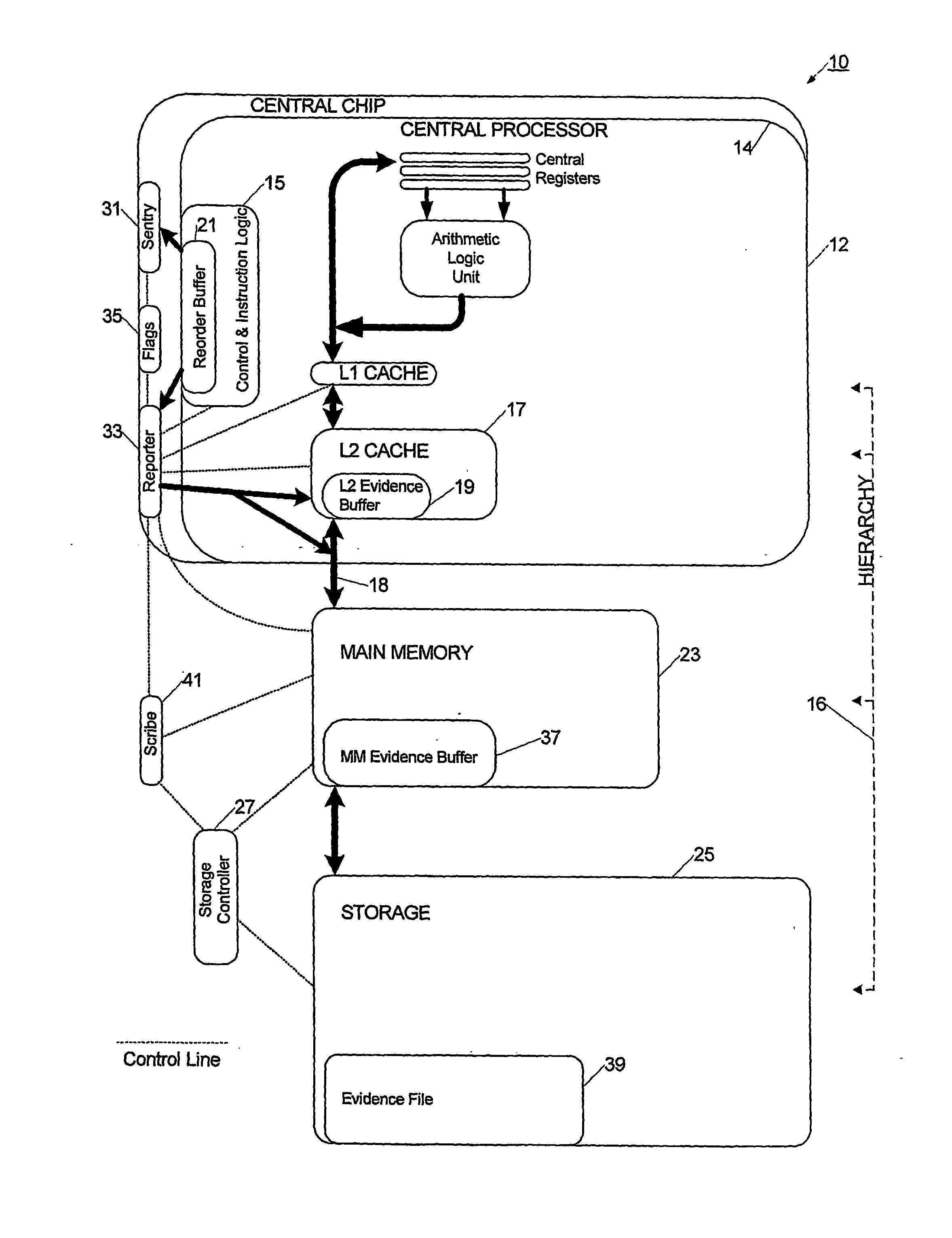
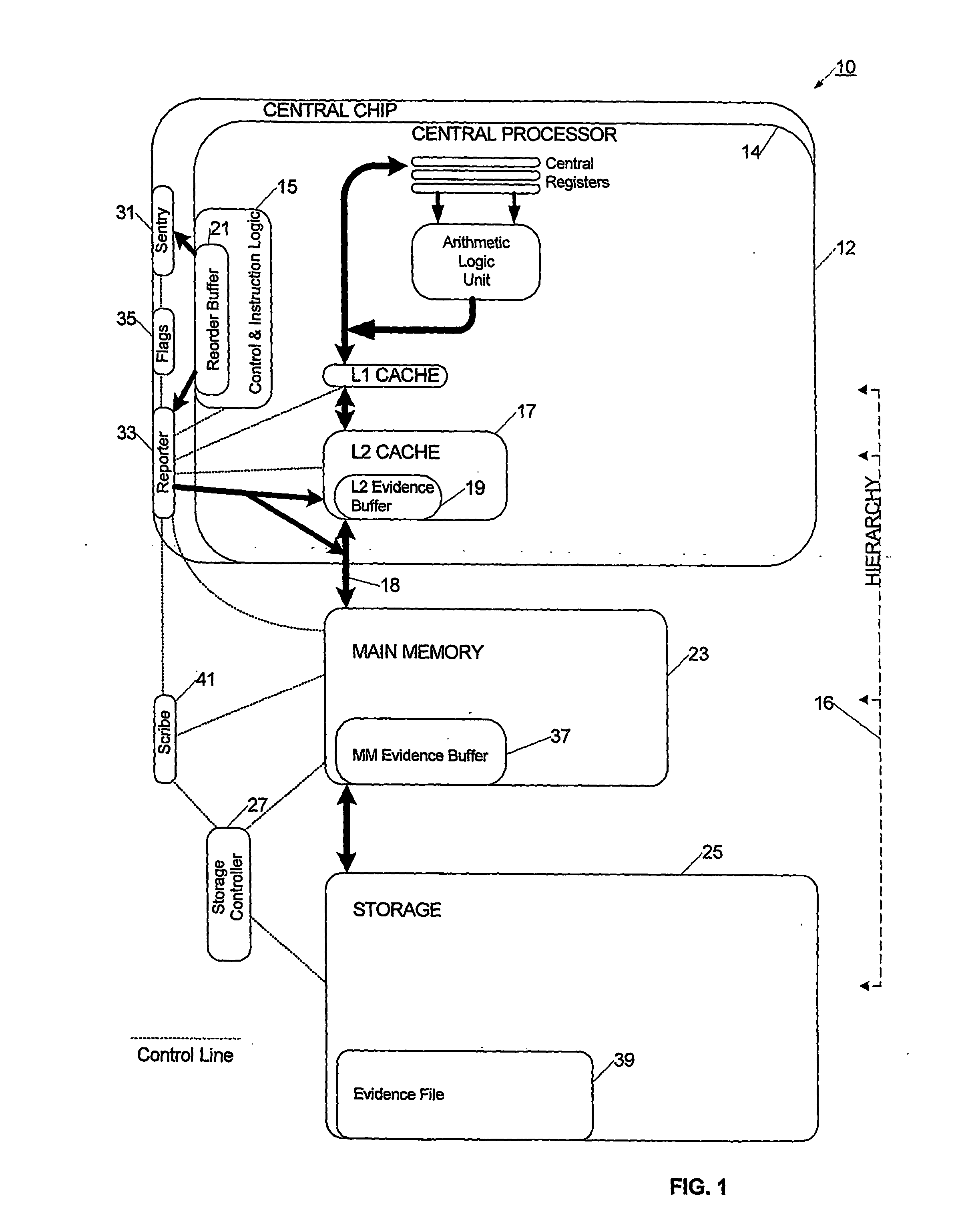
[0030]In a specific implementation of the debugging system, a fast response sentry circuit monitors a low-level asset in the processor for a predetermined software event, and upon that event, triggers a fast response reporter circuit to selectively extract data from the low-level asset. The sentry circuit and the reporter circuit each couple to sequential logic circuits, which enable more sophisticated and compound monitoring and selection. Once the data has been extracted, the data is stored in an evidence file for review and analysis. Using these means for and process of monitoring, selection, and extraction process, a user is able to efficiently focus on hypothetical areas of interest, as well as concentrate data collection on promising areas. A preparation software tool may be used to assist in configuring and setting up the reporter and the sentry. The debugging system also has tools to assist in examining the extracted evidence file. For example, an automated detective software may simplify the process of searching the evidence file for relevant evidence data.
[0031]In a particular construction of the debugging system, the fast logic circuits are integrated on-chip with the processor, thereby enabling efficient connection to the low-level assets, and causing only slight interference with the program executing on the processor. Further, the sequential logic may also be integrated on-chip as a co-processor or a thread in a multi-threading processor. The debugging system may also be constructed to take advantage of many resources available on the processor, such as controllers, cache memories, and data paths. By sharing existing resources, the debugging system may be more readily incorporated into existing chip architectures.
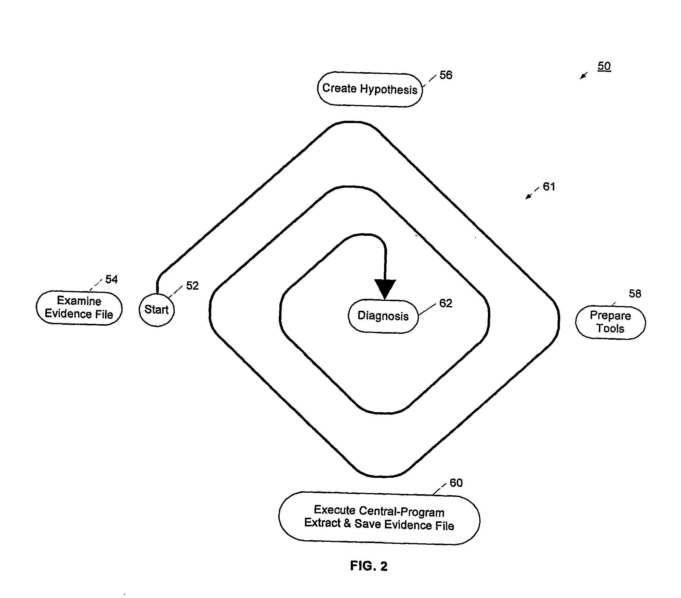
[0032]In using the debugging system, the user develops a general hypothesis as to the cause of a bug. Using preparation software, the user defines landmarks, codemarks, or other software events that may assist in locating the cause of the bug, and sets selection criteria to extract a useful quantity of evidence data. The user executes the software program, and collects selected data in an evidence file responsive to the sentry circuit detecting the software event. Using examination tools, the user reviews and analyses the evidence file, and gains insight into the location or cause of the bug. The queries developed in using the examination tools are useful in constructing the next landmarks for the sentry circuit and for the selection criteria for the reporter circuit. The user iteratively configures the debugger, collects new data, evaluates the data, and develops a more focused and concentrated hypothesis. Thus, the debugging system enables a systematic and more predictable methodology for debugging software failures.

Problems solved by technology

Briefly, the software debugging system starts with a processor that is executing a software process, and the software process has a bug or other failure.

Method used


Image

  • System and Method for Software Debugging
  • System and Method for Software Debugging
  • System and Method for Software Debugging

Examples


examples

[0058]This section teaches several examples that introduce and illustrate the usage, functions and structures of the debugging system.

example a

[0059]Earlier Evidence and Hypothesis: Suppose the operator examines earlier evidence. This shows a specific variable with two different values. During earlier execution, this variable has a correct value. During later execution, this variable has an incorrect value. Therefore the operator creates (envisions) the following crude hypothesis:[0060]There is a Precursor: Assignment of the correct value to this variable.[0061]There is a Symptom: Assignment of the incorrect value to this variable.[0062]There is a Bug: During Execution, the Bug occurs between the Precursor and Symptom.[0063]The following evidence may provide clarification: Evidence of Execution between the Precursor and Symptom.

[0064]The hypothesis concerning the Bug is quite crude. Nevertheless, often this will lead to eventual diagnosis. Therefore the operator creates (envisions) the following pseudo-code:[0065]{Landmark: Precursor} A specific (correct) value was assigned to a specific variable.[0066]{Corresponding Actio...

example b

on & Preparation

[0070]Above Example A illustrated how it is useful to detect when a specified address is assigned a specified value. Here Example B illustrates how to specify an address and to specify a value.

[0071]Address Types: Often, when a central-program is executed repeatedly, some or many addresses are the same across executions (“repeatable”) as a hexadecimal virtual address. In other cases, an address is better described (more repeatable or more understandable) in symbolic form similar to source-code. Either address style may be specified in the test for a landmark. To help the operator to examine an evidence file after execution of the central program, the debugging system provides exhibitor software and detective software. The exhibitor and detective support displaying an address as a hexadecimal virtual address, such as “0000 1B3F”. Also, the exhibitor and detective tools support displaying an address as source-code symbolic address and its context. Here context provides...


PUM


Abstract

The software debugging system provides a processor that is executing a software process, and the software process has a bug or other failure. A fast-response reporter circuit connects to a low level asset in the processor, such as a reorder buffer, commit buffer, or high speed data path. The fast response reporter circuit is configured to selectively extract data from the low-level asset, and the extracted data is transmitted to an evidence file for review and analysis. In one arrangement, a fast-response sentry circuit also connects to a low-level asset in the processor, and is configured to monitor for a predefined event. When the predefined event occurs, the fast-response sentry circuit causes an action to occur, such as activation of the reporter fast-response circuit.

Description

CROSS REFERENCE TO RELATED APPLICATIONS[0001]This application claims priority to U.S. provisional patent application No. 60 / ___,___, filed Jul. 25, 2003, entitled “Bug Tracer: Better Tool & Method to Diagnosis Software Bugs”, which is incorporated herein by reference.STATEMENT REGARDING FEDERALLY SPONSORED RESEARCH AND DEVELOPMENT[0002]Not applicable.REFERENCE TO A COMPUTER LISTING, A TABLE, OR A COMPUTER PROGRAM LISTING COMPACT DISK APPENDIX[0003]Not applicable.BACKGROUND OF THE INVENTION[0004]1. Field of the Invention[0005]The present invention relates generally to the field of hardware and software tools for software code debugging. More particularly, the present invention relates to a configurable hardware circuit interacting with a processor for the collection of debugging data.[0006]2. Description of Related Art[0007]Software debugging is the process of locating and fixing errors in a software program. Many tools have been developed to assist a developer in this process, but t...

Claims


Application Information

Patent Timeline
IPC IPC(8): G06F9/00G06FG06F11/36
CPCG06F11/3648G06F11/3636
Inventor ZINGHER, ARTHUR R.
Owner ZINGHER ARTHUR R
Learn More