
Power MESFET Rectifier

a technology of power mesfet and rectifier, which is applied in the direction of electric variable regulation, process and machine control, instruments, etc., can solve the problems of low conversion efficiency, unattractive even in low current applications, and high power loss of p-n rectifiers operating at high current conditions

Inactive Publication Date: 2008-03-20
ADVANCED ANALOGIC TECHNOLOGIES INCORPORATED
View PDF0 Cites 35 Cited by
  • Summary
  • Abstract
  • Description
  • Claims
  • Application Information

AI Technical Summary

Benefits of technology

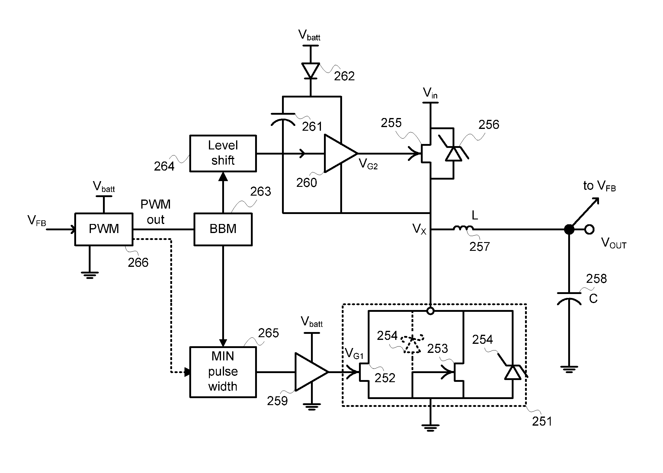
[0041]The dual mode device is ideal for use in switching regulators—as switching frequencies increases, it become increasingly difficult to enforce break before make (BBM) operation of high and low-side switches. This occurs because BBM operation requires deadtime (i.e., time in which both the high and low-side switches are off) and the amount of time available for this state shrinks as switching frequency increases. The same result occurs as duty-cycle of a switching regulator increases—time available for deadtime decreases. The dual mode device accommodates operation where the combination of duty-cycle and switching frequency prevent proper BBM operation by allowing the synchronous rectifier to be disabled. With the synchronous rectifier disabled, the MESFET rectifier provides rectification without the need for switching or deadtime.

Problems solved by technology

With such a high on-state drop, the power loss in P-N rectifiers operating at high current conditions is too high for use in most applications other than in very high-voltage high-power circuits where excess power may be removed using large heat sinks.
In lower voltage applications and especially in battery powered applications, the relatively large voltage drop in P-N junction rectifiers results in low conversion efficiency, making them unattractive even in low current applications.
Silicon P-N junction diodes also suffer from excess stored charge adversely affecting the diode's switching performance and efficiency.
In switch-mode voltage regulation, the excess charge can result in current momentarily flowing in the reverse direction through the rectifier, causing undesirable switching power losses (called reverse recovery losses), lowering efficiency, and producing unwanted electrical noise.
The stored charge of silicon P-N junction diodes essentially limits the maximum switching frequency in which such diodes can be used, typically in the sub-Megahertz range.
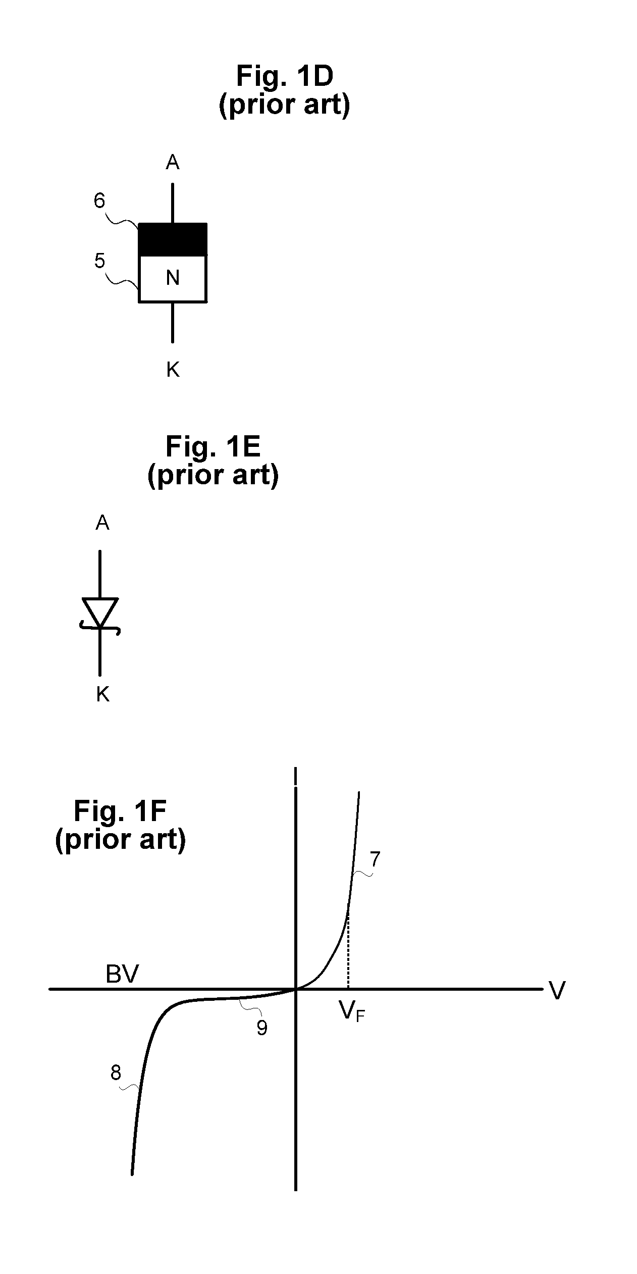
The Schottky rectifiers do however suffer from a problematic tradeoff between off-state leakage and forward voltage drop.
Excess Schottky diode leakage current lowers efficiency during converter operation and is especially problematic in any light load or sleep mode conditions where they can discharge a battery over an extended period.
The limited breakdown is further exacerbated by an undesirable phenomena know as junction barrier lowering causing a strong voltage dependence in off state leakage, essentially rendering the rectifier unusable at higher voltages.
Barrier lowering also results in adverse sensitivity of Schottky leakage current to increases in temperature—leakage further degrading the device's performance as a rectifier.
In extreme cases, leaky Schottky diodes can exhibit destructive thermal runaway in their off condition, where leakage leads to localized heating, increased barrier lowering which in turn generates even greater localized leakage current.
Unfortunately no available semiconductor rectifier today behaves with such an ideal characteristic.
Since current is flowing while voltage is present, power loss occurs in the rectifier.
While the reverse recovery power loss is easy to specify mathematically, in practice its prediction a prior / is difficult and complex since it depends on diodes properties such as the voltage ramp rate (or “snappiness”) of the diode resulting from three-dimensional minority carrier recombination effects within the device, from stray inductance in the circuit and package, and complex electro-thermal interactions.
In general, however, rectifiers that store more charge will suffer greater reverse-recovery losses.
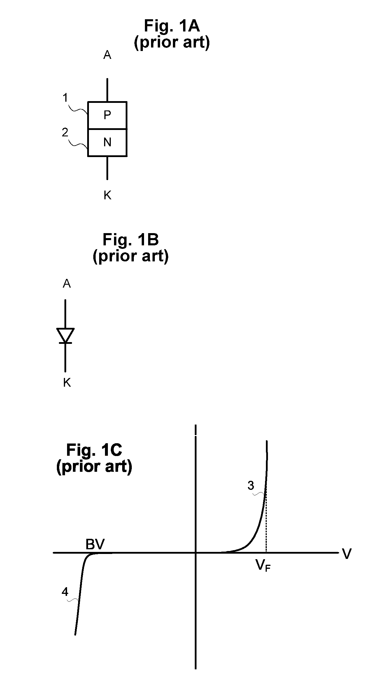
In summary, no conventional two-terminal device meets the ideal characteristic of a rectifier, i.e. a device offering low on-state voltage drop, high and robust avalanche breakdown, low off state leakage, low temperature coefficient of leakage, low stored charge, and freedom from thermal runaway.
At higher frequencies, especially above 2 MHz, two major problems emerge with using a synchronous rectifier.
First, the driving the gate capacitance of the synchronous rectifier MOSFET becomes a non-negligible power loss.
At low voltages, i.e. under 30 V, a power MOSFET's high input capacitance can be a significant and even dominant component of power loss in a switching converter.
Even more problematic, there is an intrinsic tradeoff between conduction and switching losses in a power MOSFET used as the switch or synchronous rectifier in DC-to-DC power switching converters.
Increasing the transistor's gate bias to reduce on resistance adversely impacts gate drive switching losses.
Conversely reducing gate drive improves drive losses but increases resistance and conduction losses.
Even attempts to optimize or improve the device design suffer compromises.
The second problem in increasing the frequency of switching power supplies using synchronous rectification occurs for very short pulse durations.
In such an event, there is simply not enough time to turn the synchronous rectifier on and then off again in the short time in each clock period when rectification is to occur, i.e. during inductor current recirculation.
At this condition, very little benefit is gained by synchronous rectification.
Limiting the value of D however restricts the useful voltage conversion range of the converter since in a non-isolated converter D is proportional to the converter's input-output voltage ratio.
Restricting the maximum duty cycle of a switching regulator limits its useful range of applications.
Unfortunately, present-day two-terminal rectifiers exhibit higher conduction losses than synchronous rectifiers since their voltage drop doesn't scale linearly with area as a MOSFET does.

Method used


Image

  • Power MESFET Rectifier
  • Power MESFET Rectifier
  • Power MESFET Rectifier

Examples


Embodiment Construction

[0053]Adapting MESFETs for efficient, robust, and reliable operation as rectifiers and as synchronous rectifiers for use in switching power supplies requires innovations and inventive matter regarding both their fabrication and their use. These innovations are described in the related patent applications previously identified. The design and fabrication of power MESFETs for low noise, high frequency operation with rugged avalanche characteristics, especially for use as rectifiers and synchronous in switching converters at frequencies beyond that of normal silicon MOSFETs capabilities, requires inventive matter, which is the main subject of this invention disclosure.

[0054]In another embodiment of this invention, a new MESFET merged device is optimized and used to perform both two-terminal Schottky rectification and synchronous rectification in the same device. In another embodiment of this invention, a gate control method and algorithm is used to switch between rectifier and synchron...


PUM


Abstract

A rectifier MESFET includes an N-channel MESFET having its gate connected to its source, and at the same current density having a voltage drop lower than the gate Schottky diode. A Schottky diode may be connected in parallel with the N-channel device to provide over current protection. A Zener may also be connected in parallel to provide reverse voltage protection. A second N-channel device may be connected in parallel. The addition of the second N-channel provides two different operational mode: synchronous rectification where the majority of current flows through the low resistance first N-channel device and asynchronous rectification where the majority of current flows through the somewhat higher resistance first N-channel device.

Description

RELATED APPLICATIONS [0001]This application is one of a group of concurrently filed applications that include related subject matter. The six titles in the group are: 1) High Frequency Power MESFET Gate Drive Circuits, 2) High-Frequency Power MESFET Boost Switching Power Supply, 3) Rugged MESFET for Power Applications, 4) Merged and Isolated Power MESFET Devices, 5) High-Frequency Power MESFET Buck Switching Power Supply, and 6) Power MESFET Rectifier. Each of these documents incorporates all of the others by reference.BACKGROUND OF INVENTION[0002]Rectification is a common function in all modern power electronic circuitry. Rectification performs the simple function of AC-to-DC conversion in offline power supplies as well as in DC-to-DC switching power supplies. Today, rectification is performed using P-N junction rectifiers, Schottky rectifiers, or power MOSFETs (operating as a synchronous rectifiers), each of which suffers from certain limitations, especially in high frequency DC / D...

Claims


Application Information

Patent Timeline
IPC IPC(8): H02M3/335H01L27/06H01L29/20
CPCH01L27/0605H01L29/8128H01L29/872Y02B70/1491H02M2001/0051Y02B70/1466H02M3/1588Y02B70/10H02M1/0051
Inventor WILLIAMS, RICHARD K.
Owner ADVANCED ANALOGIC TECHNOLOGIES INCORPORATED
Learn More