
Display device

a display device and display technology, applied in the direction of electrical apparatus construction details, electrical apparatus casings/cabinets/drawers, instruments, etc., can solve the problems of difficult to provide static protection on one of the surfaces of the liquid crystal display, unintended electric field applied to the liquid crystal layer, etc., to suppress the disadvantage caused by static electricity and suppress the build-up.

Active Publication Date: 2008-03-20
138 EAST LCD ADVANCEMENTS LTD +1
View PDF5 Cites 19 Cited by
  • Summary
  • Abstract
  • Description
  • Claims
  • Application Information

AI Technical Summary

Benefits of technology

[0009]An advantage of some aspects of the invention is to provide a display device wherein static protection on one of the surfaces of its display panel is easily provided.

Problems solved by technology

It should be noted that in the aforementioned related-art lateral-electric-field-mode liquid crystal display, there is a disadvantage that an unintended electric field is applied to the liquid crystal layer because of the generation of static electricity on one of the surfaces of the liquid crystal display panel (more specifically, on the side of the CF substrate on which an electrode is not formed).
However, no specific method of how the metal case should be connected to the ground potential is described.
Generally in those cases, there is not an enough space available for static protection because the lateral-electric-field-mode liquid crystal display used in those cases is small, with the result that there is a disadvantage that it is difficult to provide static protection on one of the surfaces of the liquid crystal display (more specifically, on the side of the CF substrate on which an electrode is not formed) when a liquid crystal display panel used as a car mounted head-up display is small.

Method used


Image

  • Display device
  • Display device
  • Display device

Examples


Embodiment Construction

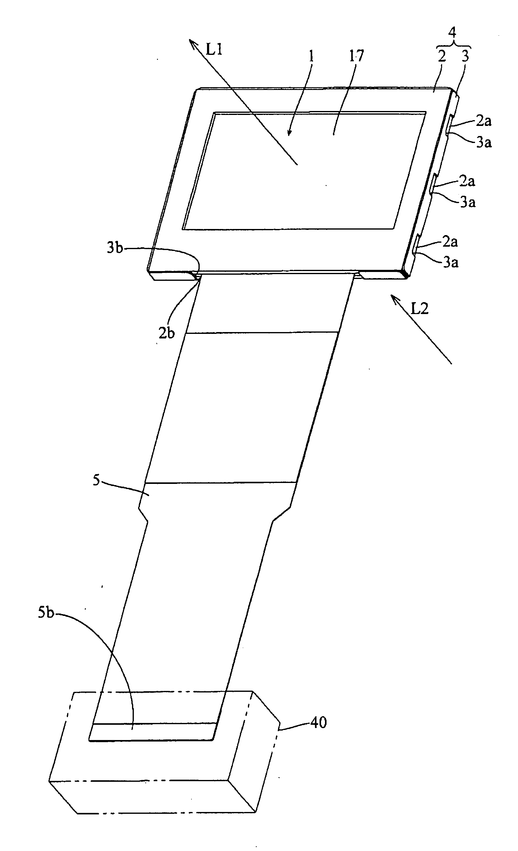
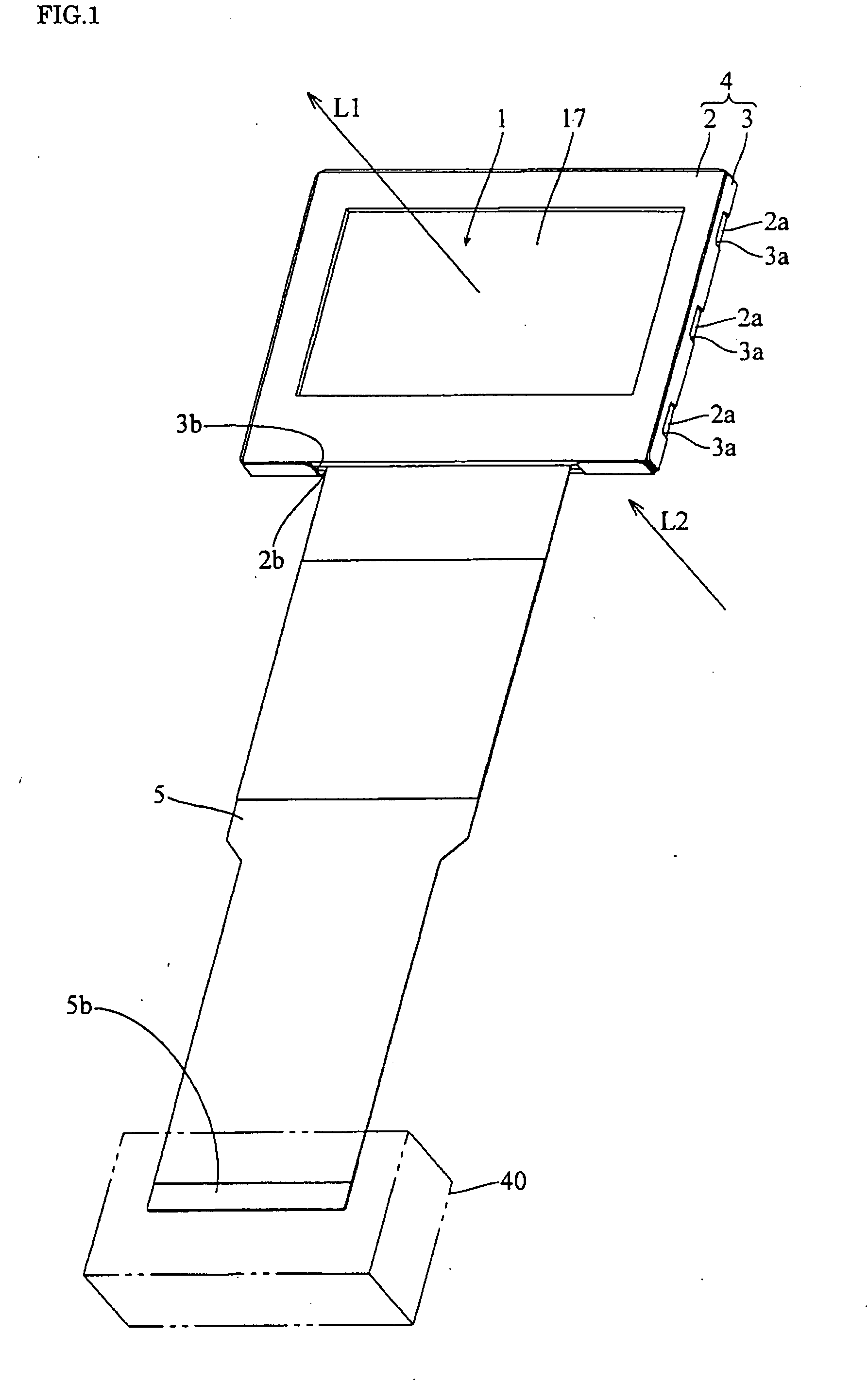
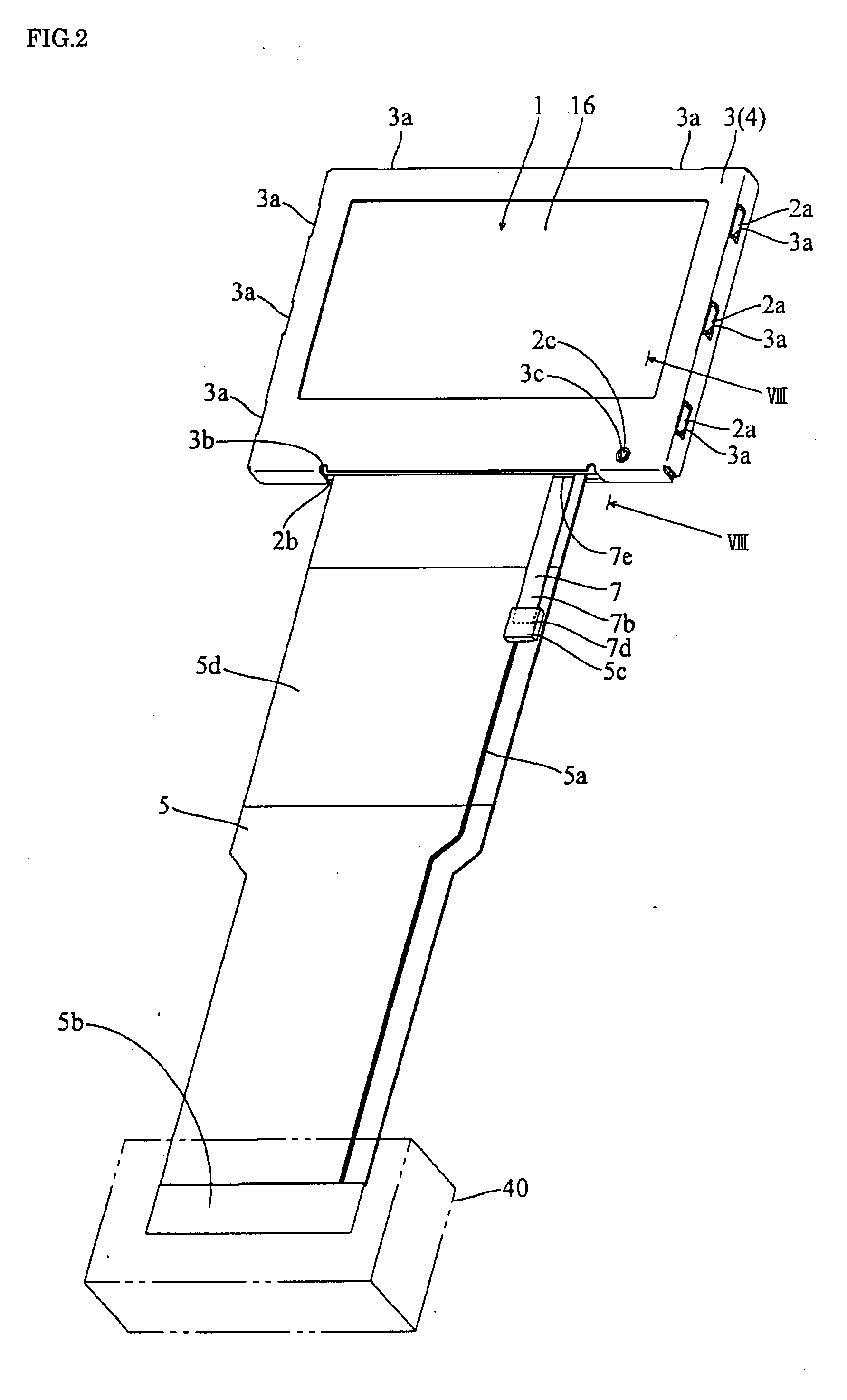
[0028]FIG. 1 is a perspective view of a head-up display (display device) according one embodiment of the present invention as seen from the front side. FIG. 2 is a perspective view of the head-up display (display device) of the present embodiment of the invention as seen from the rear side. FIG. 3 is an exploded perspective view of the head-up display according to the present embodiment of the invention as illustrated in FIGS. 1 and 2. FIG. 4 is a cross-sectional view of a liquid crystal display panel in the head-up display according to the present embodiment of the invention as illustrated in FIGS. 1 and 2. FIG. 5 is an exploded perspective-view of a front side case in the head-up display according to the present embodiment of the invention as illustrated in FIGS. 1 and 2. FIG. 6 is a perspective view of a flexible printed circuit board for static protection used for the head-up display according to the present embodiment of the invention as illustrated in FIGS. 1 and 2. FIG. 7 is ...


PUM


Abstract

A display device of the invention includes a liquid crystal display panel 1, an FPC 5, a box-formed storing case 4, and an FPC 7. The liquid crystal display panel 1 is provided with an ITO film 18 on its front side. The FPC 5 is attached to the liquid crystal display panel 1, has at least a ground line 5a, and is connected to an external device 40. The storing case 4 includes at least a rear side case (metal case) 3 electrically connected to the ITO film 18, as well as stores the liquid crystal display panel 1. The FPC 7 electrically connects the ground lines 5a of the FPC 5 and the rear side case 3. With the above-mentioned configuration, a display device can be provided wherein static protection on the front side of the display panel is easily provided.

Description

BACKGROUND[0001]1. Technical Field[0002]The present invention relates to a display device, and more particularly to a display device such as a liquid crystal display.[0003]2. Related Art[0004]As a related-art display device, a liquid crystal display which uses changes of the optical property of liquid crystal for displaying characters and / or images is known. Related-art liquid crystal displays include a vertical-electric-field-mode or lateral-electric-field-mode liquid crystal display.[0005]Generally, related-art liquid crystal displays include a liquid crystal display panel having a structure in which a TFT and a CF substrates are placed facing each other and sandwiching a liquid crystal layer therebetween. The TFT substrate is a substrate onto which a thin-film transistor (TFT) is built on the surface thereof facing the CF substrate. The CF substrate is a substrate on which a color filter (CF) is formed on the surface thereof facing the TFT substrate. In a related-art vertical-ele...

Claims


Application Information

Patent Timeline
IPC IPC(8): H05K5/04
CPCG02F1/13452H05K1/0215H05K2201/058H05K9/0054H05K9/0067H05K1/147
Inventor NOGUCHI, SATOSHIMAETA, HIROYASUKINUGAWA, TOMOKATSU
Owner 138 EAST LCD ADVANCEMENTS LTD
Learn More