Systems and Methods for Generating Compost

Inactive Publication Date: 2008-03-13
ENGINEERED COMPOST SYST
View PDF11 Cites 15 Cited by
  • Summary
  • Abstract
  • Description
  • Claims
  • Application Information

AI Technical Summary

Benefits of technology

[0012] Systems and methods for generating compost utilizing aeration are provided. The systems disclosed herein are capable of controlling compost odors, maintaining the desired oxygen levels in the biomass, and minimizing evaporative drying of the biomass. The disclosed systems and methods for generating compost may utilize negative or positive aeration.
[0014] The compost cover is formed of a material that is substantially gas and liquid impermeable, and is provided a plurality of aeration ports, or orifices, that permit the passage of gases through the cover. The size and number of aeration ports may be varied to meet the air-flow requirements for given biomass, or feed stocks, zone size and process goals. The compost cover is generally constructed of fabric that is durable, flexible, UV resistant, waterproof, and relatively light-weight.
[0015] The aeration floor may be constructed of concrete or the like, and has a generally flat, planar working surface. The surface of the aeration floor is provided with a plurality of gas flow apertures, or orifices, that connect to at least one gas flow pipe, or channel, installed below grade. In certain embodiments, a network of gas flow pipes and / or channels is provided. An air suction manifold is sealably and removably connected to at least one outlet of the network of gas flow channels and / or pipes, providing air removal from the compost biomass. The air suction manifold draws air and / or other gases downwards from the bottom area of the biomass, through the plurality of gas flow apertures in the aeration floor, and into the network of gas flow channels and / or pipes. The air travels through the network of channels and / or pipes and is conveyed towards the outlet. The air then passes through the air suction manifold to an air distributor that is sealably and removably connected to the air suction manifold. Through the air distributor, the air from the compost biomass is distributed towards a discharge manifold that directs the air towards an odor control device, such as a biofilter, where the air is treated to substantially eliminate compost odors.
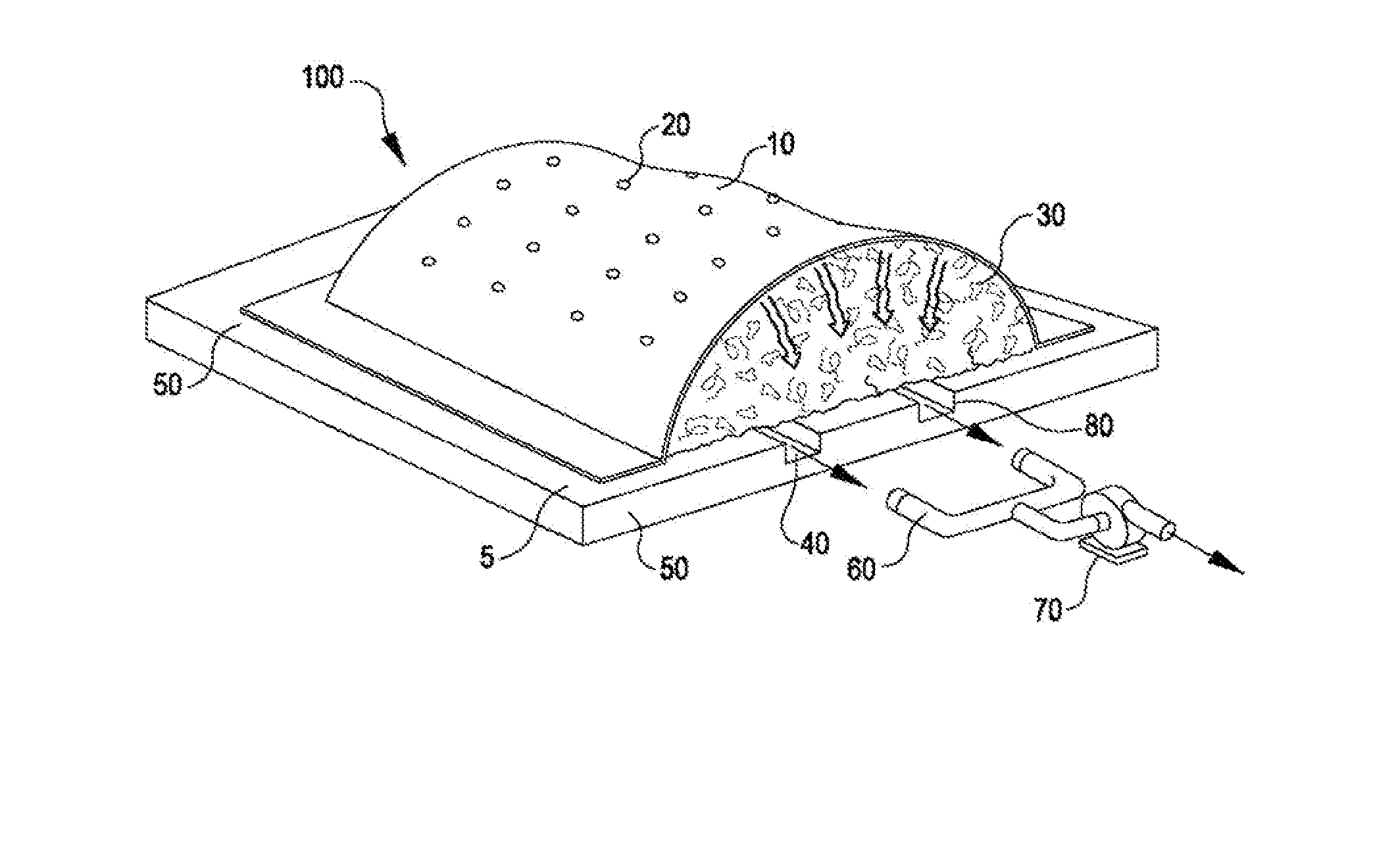
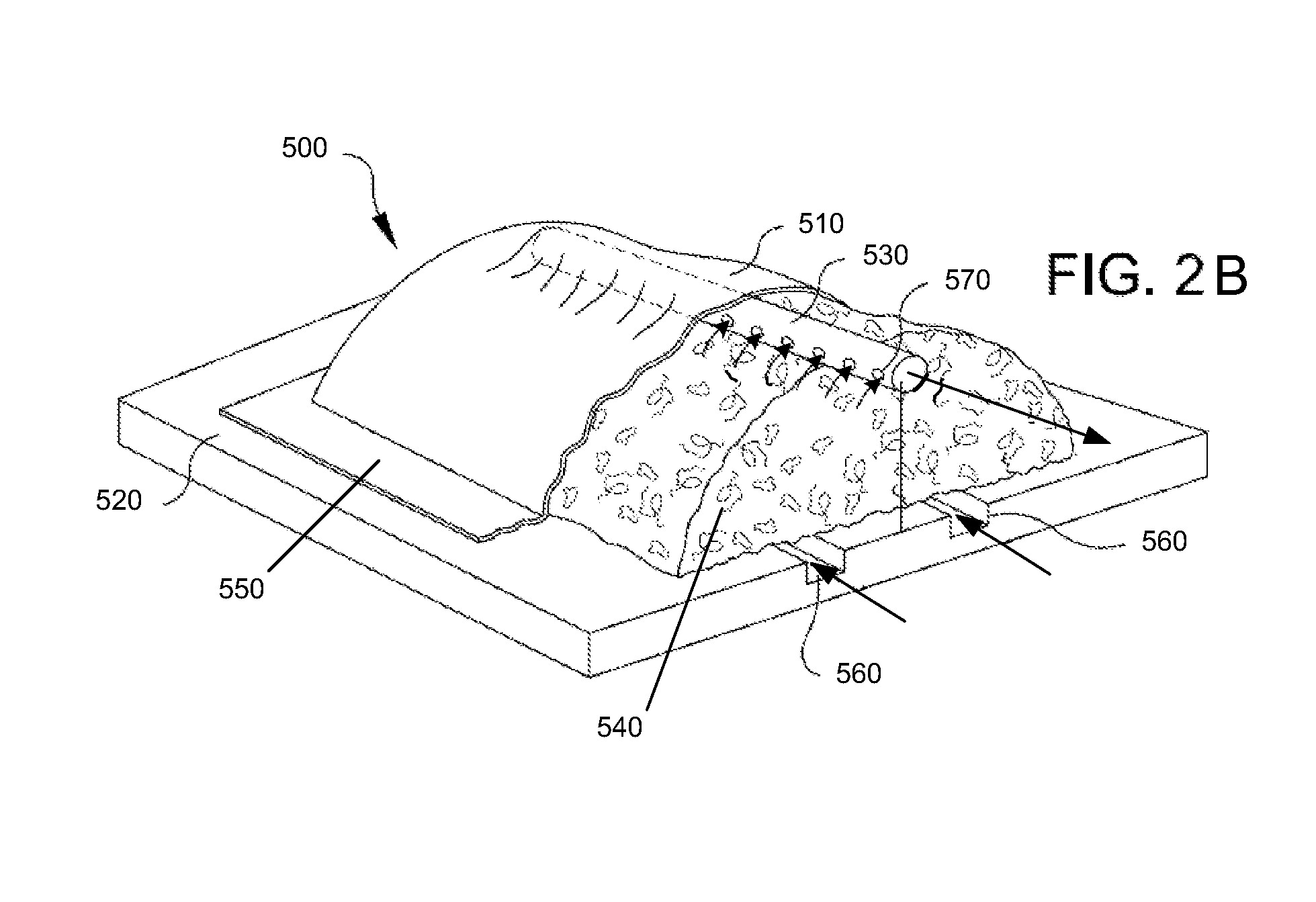
[0020] In other embodiments, positive aeration composting systems are provided. In one such embodiment, the composting system comprises a compost cover, a positively aerated floor, and a suction system positioned in proximity to, or associated with, the compost cover and located near a top of a biomass pile. Biomass for use in generating compost is placed on the positively aerated floor, and the compost cover is placed over the biomass. The edges of the compost cover, which substantially covers the biomass, may be weighted and / or connected to the positively aerated floor by way of strapping means connected to fastening points in the positively aerated floor, in order to provide a loose seal to the positively aerated floor. During operation, air flow drawn by the suction system at the top of the biomass pile maintains a negative pressure across the compost cover, thereby generating suction between the compost cover and the top of the compost biomass pile. The suction causes the compost cover to be substantially sealed onto the top of the compost biomass pile, preventing release of gasses from the biomass to the atmosphere.
[0021] In one embodiment, the compost cover is formed of a material that is substantially gas and liquid impermeable. In another embodiment, the compost cover is formed of a material that is semi-permeable. The compost cover is generally constructed of fabric that is flexible, durable, UV resistant, waterproof, and relatively light-weight.
[0026] The aeration vault may be left open at one or both ends whereby air can flow freely through the aeration vault via the open ends, allowing the compost biomass pile to be aerated. Alternatively, the one end of the aeration vault may be connected to a forced air aeration system, allowing induced aeration to take place within the negative or positive aeration composting system, wherein desirable oxygen and temperature levels of the compost biomass pile can be controlled and maintained, and the production of compost odors can be substantially eliminated.

Problems solved by technology

Composting systems that utilize positive aeration have the disadvantage that ammonia and other odorous and / or corrosive gases are released from the surface of the compost pile.
Systems that employ negative aeration usually have operational problems associated with the collection, removal and disposal of particulate matter and moisture drawn into the aeration networks.
However, these systems are commonly associated with significant compost odor emissions due to low oxygen levels, uncontrolled temperatures, and open compost piles.
They have the disadvantage that they do not control compost odors and are water-absorbent, and can therefore become heavy and difficult to transport.
They can only be used with composting systems that involve positive aeration and require weighted edges to hold the covers in place as the covers tend to “balloon”, due to gas flow constriction through the fabric.
The low air flow rates result in low oxygen levels and very high temperatures of the biomass.
These conditions reduce the efficiency of the aerobic bacteria that generate the compost.
Further, micro-porous covers provide little thermal insulation, are quite heavy and are very expensive.
However, the resulting aeration is very uneven radially about and along the axis of the sleeve.
As a result, the generated compost is usually dry on top and saturated with moisture at the bottom.
Further, foul leachate is often released onto the ground and surroundings when the plastic sleeve is removed.
Compost generated using these plastic sleeves often requires significant additional processing to obtain stability.

Method used


Image

  • Systems and Methods for Generating Compost
  • Systems and Methods for Generating Compost
  • Systems and Methods for Generating Compost

Examples


Embodiment Construction

[0036] Systems and methods for generating compost that employ aeration to aerobically degrade and stabilize organic wastes are provided. The composting systems disclosed herein are capable of effectively controlling compost odors, maintaining desired oxygen levels in the biomass, and minimizing evaporative drying of the biomass.

[0037] In the embodiment shown in FIG. 1, negative aeration composting system 100 comprises at least one aerated composting zone 5. Composting system 100 is provided with a compost cover 10 and an aeration floor 50. Compost biomass 30 for use in generating compost is placed on aeration floor 50, and compost cover 10 is placed over and substantially covers biomass 30. The edges of compost cover 10 may be weighted and / or may be provided with straps that connect to fastening points in aeration floor 50. Compost cover 10 is further held in place by way of suction generated from aeration floor 50. A central aeration and control system (not illustrated) controls t...


PUM


Abstract

Systems and methods for the generation of compost are provided. In one embodiment, the system for generating compost comprises a positively aerated floor, a semi gas and liquid impermeable compost cover sized to cover a compost biomass pile placed on the positively aerated floor, and a suction system positioned under or substantially close to the compost cover and generally near a top of the compost biomass pile, wherein the floor comprises a plurality of channels connected to at least one gas flow pipe installed below or above grade, wherein gas drawn by suction system at the top of the biomass compost pile maintains a negative pressure across the compost cover, thereby generating suction between the compost cover and the top of the compost biomass pile, and wherein the compost cover directs substantially all of the gas flow towards the suction system.

Description

REFERENCE TO RELATED APPLICATIONS [0001] This application is a continuation-in-part of U.S. application Ser. No. 10 / 557,924, filed Nov. 8, 2006, which claims priority to U.S. provisional patent application No. 60 / 735,994 filed Nov. 9, 2005.FIELD OF THE INVENTION [0002] This invention generally relates to systems and methods for generating compost. More particularly, the invention relates to an aerated compost generation system that provides substantial reduction of compost odor emission and evaporative drying of compost. BACKGROUND OF THE INVENTION [0003] Composting is an effective waste management tool used to convert organic wastes into useful products. Various systems and methods for generating compost to improve the disposal and the beneficial re-use of organic wastes, such as garden waste, bio-solids, agricultural waste, municipal solid waste and the like, are known. Many of these systems and methods focus on the improvement of compost odor control, the rapid stabilization of c...

Claims


Application Information

Patent Timeline
IPC IPC(8): C12M1/04C05F9/00
CPCC05F17/027C05F17/0258Y02P20/145C05F17/979C05F17/964Y02W30/40
Inventor O'NEILL, F. T.HIBBARD, CHRISTOPHER J.KRAUTER, CHARLES A.
Owner ENGINEERED COMPOST SYST
Why Eureka
Try Eureka