Eureka AIR delivers breakthrough ideas for toughest innovation challenges, trusted by R&D personnel around the world.

Process and apparatus for loading a particulate solid into a vertical tube

a technology of elastic fluid and particulate solid, which is applied in the direction of liquid-gas reaction process, chemical/physical/physical-chemical stationary reactor, chemical/physical process, etc., can solve the problems of high operating temperature and/or high pressure, reactors may have to withstand high thermal and pressure stresses, and are subjected to crushing force, etc., to reduce the imposition of crushing force, facilitate the removal of fragments, and minimise the effect of pressure drop across the catalyst bed

Inactive Publication Date: 2004-07-29
JOHNSON MATTHEY DAVY TECH LTD
View PDF29 Cites 10 Cited by
  • Summary
  • Abstract
  • Description
  • Claims
  • Application Information

AI Technical Summary

Benefits of technology

[0033] The present invention accordingly seeks to provide a novel process for effecting contact between an elastic fluid, such as a gas or vapour, and a particulate solid under conditions which include use of cycling between elevated temperatures and ambient or near ambient temperature but under which crushing of the solid particles is minimised. It further seeks to provide an improved process in which a gas or vapour is contacted with a particulate solid, such as a catalyst, desiccant or adsorbent, which is subjected to elevated temperatures of several hundreds of degrees Centigrade and then cooled without subjecting the particulate solid to undue mechanical stresses. In addition, the present invention seeks to provide a process for contacting a gas or vapour with a particulate solid in a tube at elevated temperatures under conditions which minimise imposition of crushing forces on the solid, particularly during cooling of the tube, and which facilitate removal of fragments of the particulate solid formed by attrition of the particles of catalyst or other solid so as substantially to obviate any significant increase of pressure drop. Furthermore the invention seeks to provide a new and improved method of packing a catalyst bed. Yet another objective of the present invention is to provide a method of operating a catalytic reactor tube packed with catalyst particles wherein the position of the top of the catalyst bed is known with certainty despite the use of elevated temperatures which cause the reactor tube to expand both longitudinally and radially. The invention further seeks to provide a method of operating a catalytic reactor, more particularly a tubular reactor in which a gaseous or vaporous phase is contacted with a particulate catalyst, so that the pressure drop across the catalyst bed is minimised. It also seeks to provide a method of loading a tubular reactor with a particulate material, such as a particulate catalyst, in which the production of undersized "fines" particles is substantially obviated and in which any such "fines" particles can be removed from the catalyst bed without first discharging the catalyst from the reactor.
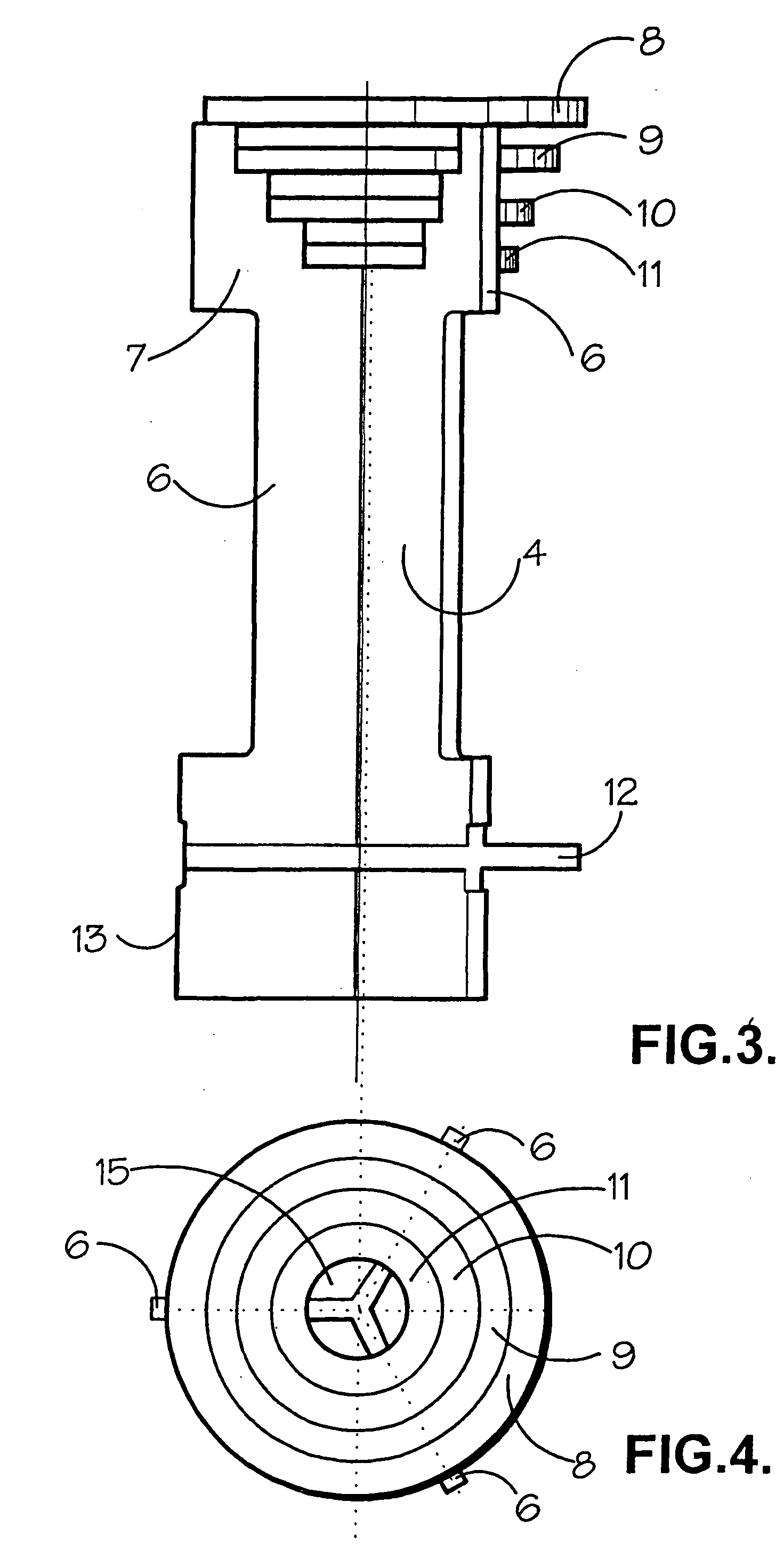
[0045] The follower means is desirably designed so that there is a gap or gaps through and / or around it for upward flow of elastic fluid therethrough. Moreover the lower end of the containment zone is desirably designed so that, when there is no upward flow of elastic fluid through the containment zone, yet there is a gap or gaps for elastic fluid to flow upwardly through or around the follower means when such upward flow commences but remains below the threshold rate. Thus the follower means typically includes a piston portion which is a loose fit in the containment zone so that fluid can pass up through an annular gap surrounding the piston portion. This piston portion can be disposed at or towards the lower end of the follower means, at or towards the upper end of the follower means, or intermediate the upper and lower ends of the follower means. One of the functions of the follower means is to support the charge of particulate solid when any upward flow of fluid is insufficient to cause particulate solid to rise upwardly in the containment zone to form a cushion against the underside of the upper retainer means. If the piston portion is at or near the upper end of the follower means, then the piston portion can perform this function; if not, then the follower means preferably includes, at or towards its upper end, support means for supporting the charge of particulate solid when any upward flow of fluid is insufficient to cause particulate solid to rise upwardly in the containment zone to form a cushion of particulate solid against the underside of the upper retainer means, for example a series of concentric rings spaced one from another so that the gaps between adjacent pairs of rings are insufficient to allow a particle of predetermined size of the particulate solid to pass therethrough. Such gaps also assist in distributing the flow of upflowing elastic fluid more uniformly across the cross-section of the containment zone.
[0048] Alternatively, the piston portion can be provided with a central vertical rod with one or more spider sets formed by three or more rods or bars radiating from the central vertical rod, for example three radiating rods set at an angle of approximately 120.degree. to one another and positioned so as to prevent the follower means from tilting a significant amount as it moves within the containment zone and hence from jamming against the walls of the containment zone. In this way the follower means can allow elastic fluid to pass freely at all times around it in either the upward or downward direction, while ensuring that, as the rate of upward flow of elastic fluid is increased to a rate beyond the threshold rate, the follower means lifts smoothly off from its position at the bottom end of the containment zone and then moves up the containment zone until it abuts against the underside of the cushion of particulate solid.
[0055] Although it will frequently be preferred for the containment zone to be of substantially uniform cross-section throughout its height, it is alternatively possible for a lower portion of the containment zone in which the follower means moves in operation to have a smaller area of cross-section than an upper part of the containment zone. Hence the containment zone can comprise a lower tubular portion of relatively small diameter attached to the bottom of a tube of larger diameter. In this case, while the narrower lower portion of the containment zone in which the follower means moves in operation requires to be machined to a relatively close tolerance, the transverse dimensions of the upper portion of the containment zone do not have to be so carefully controlled. A further advantage in such an arrangement is that the gap between the follower means and the walls of the lower portion of the containment zone can be larger than if the follower means is arranged to slide in a larger tube. Again this factor reduces the need for careful machining of the inside of that part of the containment zone in which the follower means moves.
[0060] One method of loading the particulate solid into the containment zone involves loading via the top of the containment zone against a gentle upflow stream of elastic fluid at a rate less than that required to lift fully any already charged particulate solid (or to move the follower means upwardly) but such that the particulate solid does not fall freely under gravity. In this way the danger of damage to the particulate solid can be significantly reduced or substantially eliminated.

Problems solved by technology

The conditions used in such processes often include high operating temperatures and / or high pressures.
Hence reactors may have to withstand high thermal and pressure stresses.
Then when the temperature is later lowered, the walls of the reactor contract as it cools and the particulate matter may be caught as if by a tightening corset and thereby subjected to a crushing force, particularly if the particulate solid is contained in a substantially vertical metal tube.
However, in so-called fired processes which utilise high temperature operations, typically involving combustion in order to maintain the temperature in endothermic catalytic processes such as steam reforming, or in exothermic catalytic processes such as partial oxidation processes, the amounts of expansion involved are considerable.
However, if the catalyst particles are contained in a narrow vertical tube having, for example, a nominal diameter of less than about 6 inches (about 15.24 cm), this relative movement is insufficient and very high crushing forces can be generated.
This tends to result in attrition of the particulate matter, if friable to any degree, or in damage to the tube wall, if not.
Furthermore, in cases where the vertical tubes are very long and experience considerable expansion over their length due to the high operating temperature being used, for example steam reformer tubes, the particulate matter drops by a very significant amount but cannot rise back up the tube when it cools due to being tightly squeezed by the cooling tube, a factor that exacerbates the crushing tendency.
Repeated heating and cooling cycles lead to a deterioration in the desired characteristics of the packed bed, in that the originally loaded volume of particulates is compressed to a higher density, thereby increasing the pressure drop.
In addition it has been found that increased pressure drop through a catalyst bed can be caused by, amongst other reasons, breakage of catalyst particles resulting from incorrect charging of the catalyst or from differential expansion and contraction between the catalyst and the containing vessel due to temperature cycling at start-up and shut-down.
This increased pressure drop generally increases the costs associated with gas compression in all fixed bed applications.
In parallel fixed bed applications this can lead to increasing maldistribution, especially in a multi-tubular reactor, thereby causing different conversions and selectivities in different tubes.
This, in turn, can lead to further problems such as carbon laydown, formation of hot spots (leading to possible tube failure and / or to sintering of the catalyst), and to development of different rates of catalyst deactivation which can further exacerbate the situation.
Loss of catalyst surface material by spalling and attrition is particularly serious when the active part of the catalyst is in the form of a shallow surface layer, because in this case considerable catalyst activity can be lost or the catalyst activity can become maldistributed.
The debris from the crushing forces will accumulate in the, by now, more dense bed and also increase the pressure drop.
There will be an increased likelihood of different pressure drops between different tubes in a multi-tubular reactor leading to maldistribution of the gas or vapour.
In addition, the position of the top of the bed within any individual tube will be difficult to predict.
Another problem occurs with externally fired tubular reactors, such as reformers, in that any part of the tube that does not contain catalyst is liable to overheat, with a consequent danger of tube failure, since there is no endothermic reaction being catalysed in that part of the tube to absorb the radiant heat and hence to cool that part of the tube.
However, these prior art proposals are elaborate and do not solve satisfactorily the problem of crushing of particulate catalysts which can be caused by repeated temperature cycling of a reactor tube.
This screening step constitutes a costly procedure both in terms of finance and time.
Once loaded, catalyst particles usually cannot be re-arranged and the packed density only tends to increase.
In this procedure the purging gas, such as air, is passed through the catalyst bed at a linear flow velocity sufficient to fluidise the catalyst fines but insufficient to fluidise the catalyst bodies.

Method used


Image

  • Process and apparatus for loading a particulate solid into a vertical tube
  • Process and apparatus for loading a particulate solid into a vertical tube
  • Process and apparatus for loading a particulate solid into a vertical tube

Examples


example 1

[0108] A glass tube 1, which was 2 metres long with an internal diameter of 38.1 mm, was set up vertically with a follower 4 of the type illustrated in FIGS. 1 to 4 initially positioned at its bottom end. This follower 4 had a disc 12 of diameter 36 mm. A charge of 1.84 kg of a nickel catalyst (nickel on calcia-alumina support catalyst balls of nominal diameter 6 mm) was dropped carefully into the tube. After loading, the upper perforate retainer 3 was fitted at a desired height in the tube 1. This retainer consisted of a Johnson wedge-wire screen comprising 1.5 mm wire with a 2 mm gap. The tube 1 was not filled fully to allow for the lower bulk density of the catalyst during the tests. Compressed air was introduced via a pressure regulator and flow rotameter (not shown) to the bottom of the tube 1 at a rate at least sufficient to lift the catalyst and the catalyst follower 4 such that a consolidated cushion of catalyst balls 5 was formed at the top of the tube 1 immediately under t...

example 2

[0109] The weight of catalyst used in Example 1 was checked after 10, 20, 120 and 360 tests and showed 0.38% weight loss over 360 tests. In separate tests in the same apparatus the flow resistance of the fresh and worn catalyst particles used in Example 1 was compared. At an air flow rate of 49.14 Nm.sup.3 / h the fresh catalyst particles exhibited a pressure drop of 1.21.times.10.sup.5 Pa / m, while at an air flow rate of 48.96 Nm.sup.3 / h the worn catalyst particles, after 360 tests, exhibited a flow resistance of 1.22.times.10.sup.5 Pa / m.

example 3

[0110] The procedure of Example 1 was followed using 2.06 kg of nickel on .alpha.-alumina support catalyst balls of nominal diameter 6 mm from Dycat, Type 54 / 98. This catalyst support material is much more friable than that used in Examples 1 and 2 with only about 25% of the crush strength of the catalyst used in Examples 1 and 2. The weight of the catalyst was checked after 10, 60, 150, 300 and 390 tests and showed a total weight loss of 7.0% over 390 tests. During the tests catalyst fragments represented by this weight loss were visibly removed from the bed by the gas flow as dust. The amount lost in each group of tests decreased as follows, expressed as average weight % lost per lift and drop cycle: 0.085, 0.042, 0.026, 0.010, 0.009.


PUM

PropertyMeasurementUnit
internal diameteraaaaaaaaaa

Abstract

A process is described in which an elastic fluid is contacted with a particulate solid. This comprises providing a substantially vertical elongate tubular containment zone (1) containing a charge of the particulate solid (5), the volume of the containment zone (1) being greater than the settled volume of the particulate solid (5). An upper retainer means (3) is mounted at the upper end of the containment zone (1), the upper retainer means (3) being permeable to the fluid but adapted to retain particulate solid (5) in the containment zone (1). A follower means (4) is movably mounted in the containment zone (1) beneath the charge of particulate solid (5) for movement upwardly from the lower end of the containment zone (1) upon upward flow of elastic fluid through the containment zone (1) at a rate beyond a threshold rate. In the process the elastic fluid is caused to flow upwardly through the containment zone (1) at a rate which is sufficient to cause particulate solid (5) to rise up towards the upper end of the containment zone and form a cushion of particulate solid (5) against the underside of the upper retainer means (3). This rate is in excess of the threshold rate so as to cause the follower means (4) to move upwardly until it abuts against the underside of the cushion of particulate solid (5). The invention also provides an apparatus suitable for carrying out such a process and a method of loading a particulate solid into a substantially vertical tube.

Description

1. TECHNICAL FIELD OF THE INVENTION[0001] This invention relates to a process for contacting an elastic fluid with a particulate solid.2. BACKGROUND OF THE INVENTION[0002] There are many processes which involve contact between an elastic fluid, such as a gas or vapour, and a particulate solid. Thus many chemical processes are carried out using gas phase or vapour phase reaction conditions in which a gas or vapour stream is contacted with a particulate catalyst. Other processes in which an elastic fluid is contacted with a particulate solid include drying, in which a gas or vapour is contacted with a desiccant, and adsorption, in which a gas or vapour is contacted with an absorbent for the purpose of, for example, adsorption of potential catalyst poisons therefrom.[0003] In such processes the particulate catalyst or other particulate solid is frequently in the form of a fixed bed, although some processes are operated using a fluidised catalyst bed.[0004] The conditions used in such p...

Claims


Application Information

Patent Timeline
Patent Type & Authority Applications(United States)
IPC IPC(8): B01J8/00B01J8/02B01J8/04B01J8/06C01B3/38C01B3/44
CPCB01J8/0025B01J8/008B01J8/06B01J8/062B01J2208/00309C01B2203/0866B01J2208/00752B01J2208/00884C01B3/384C01B2203/0811C01B2203/0816B01J2208/0069
Inventor BENCE, ROGER KENNETHHILTON, MICHAELLINTHWAITE, MARK ANDREW
Owner JOHNSON MATTHEY DAVY TECH LTD
Why Eureka
Eureka Blog
Learn More