Wireless Communication Terminal and Control Method Threrof

a technology of wireless communication terminal and control method, which is applied in the direction of wireless communication, substation equipment, power management, etc., can solve the problems of increasing current consumption and increasing power consumption, and achieve the effect of preventing the decrease of operating reliability, enhancing operating reliability, and eliminating the burden of conducting compatibility tests

Inactive Publication Date: 2008-03-06
GE TECH DEV INC GETD
View PDF12 Cites 3 Cited by
  • Summary
  • Abstract
  • Description
  • Claims
  • Application Information

AI Technical Summary

Benefits of technology

[0030] As described above, according to the present invention, a transmission-output upper limit up to which the wireless communication terminal can operate normally is set assuming power supplied from the host device, and the maximum transmission output of the wireless communication terminal is restricted based on this transmission-output upper limit. Therefore, even if the performance of power supplied from the host device is low, transmission operation can be performed within an output range adjusted to the performance of the power supply. This prevents the wireless communication terminal from exhibiting an abnormal operation or experiencing shutdown or communication breakdown, thereby enhancing the operating reliability. Therefore, irrespective of a transmission output increased by an abrupt change in communication environments, the operating reliability is prevented from decreasing.
[0031] Furthermore, since the transmission-output upper limit is set in accordance with the actual performance of the power supplied from the host device to the wireless communication terminal, a problem with compatibility in power supply performance between the host device and the wireless communication terminal can be overcome, thereby eliminating the burden of conducting a compatibility test. Moreover, even in a case where the conventional wireless communication terminal could not be used as-is due to insufficient power supply performance, the wireless communication terminal can now be used without the burdensome work of securing power for the wireless communication terminal by connecting to another power supply port using, for example, a connection cable.
[0032] In addition, a transmission-output upper limit can be obtained without requiring a high-output transmission operation by applying supply voltage to a load circuit with variable load values or measuring the drop in supply voltage while a terminating circuit is connected to the output stage of the wireless communication terminal.
[0033] Furthermore, according to the structure where the above-described load circuit is employed, since it is not necessary to provide, for example, a switching element at the output stage of the wireless communication circuit, the present invention can be applied without causing loss at the output stage.
[0034] In addition, according to the structure where the terminating circuit is connected to the output stage of the wireless communication terminal, it is not necessary to prepare, for example, a load circuit separately from the wireless communication circuit. This affords an advantage in that the present invention can be applied on a small circuit scale.
[0035] Furthermore, the wireless communication terminal measures the transmission-output upper limit upon receiving an instruction from the host device, whereas the host device saves the transmission-output upper limit acquired from the wireless communication terminal. In this manner, transmission-output upper limit measurement operation by the wireless communication terminal can be minimized by supplying the saved transmission-output upper limit to the wireless communication terminal for communication processing during normal operation and, as required, by instructing the wireless communication terminal to measure a transmission-output upper limit. By doing so, a time loss accompanying transmission-output upper-limit measurement operation is suppressed, thereby affording an advantage in that if the host device is driven on a built-in battery, saving in the built-in battery is achieved.

Problems solved by technology

In wireless communication techniques supporting recent high data communication speeds and cellular systems, unlike wireless LANs, assumed to be used in wide areas (e.g., CDMA2000 and W-CDMA), baseband processors such as high-speed CPUs and maximum transmission powers of 20 dBm (100 mW) or more are required, which leads to more power consumption.
On the other hand, a terminal located distant from a base station performs transmission (communication) with a high output, which causes the current consumption to increase.

Method used


Image

  • Wireless Communication Terminal and Control Method Threrof
  • Wireless Communication Terminal and Control Method Threrof
  • Wireless Communication Terminal and Control Method Threrof

Examples


first embodiment

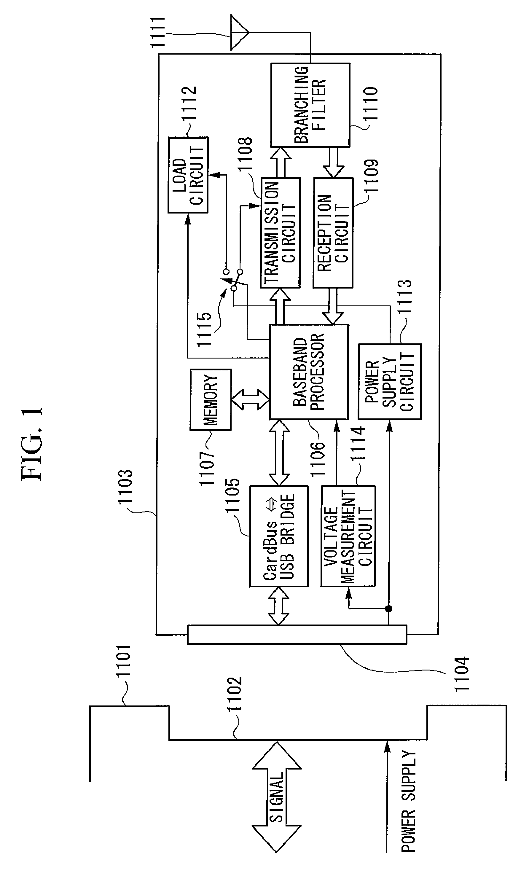
[0089]FIG. 1 is a schematic block diagram depicting the structure of a PC card communication terminal according to the present invention. In the same figure, reference numeral 1101 denotes a host device, such as a so-called notebook PC, having a PC card slot 1102. Reference numeral 1103 denotes a PC card terminal which includes a 32-bit Card Bus connector 1104. This PC card terminal 1103 is mounted in the host device 1 for use and is supplied with power from the host device 1101 to operate, controlled using, for example, the AT command.

[0090] In this PC card terminal 1103, reference numeral 1105 denotes a bridge that connects a Card Bus and a USB (universal serial bus), reference numeral 1106 denotes a baseband processor that performs communication control, reference numeral 1107 denotes a memory used by the baseband processor 1106, reference numeral 1108 denotes a transmission circuit, reference numeral 1109 denotes a reception circuit, reference numeral 1110 denotes a branching fi...

third embodiment

[0109] the present invention will now be described. It is assumed that the host device has a preinstalled OS (operating system) which provides a function for detecting a PC card terminal mounted in the PC card slot.

[0110] When the PC card terminal is inserted in the PC card slot for the first time, the host device reads out information such as the device type from the PC card terminal to install the corresponding driver software. Thereafter, each time the same card terminal is inserted in the card slot, the host device reads out the corresponding driver software from, for example, the hard disk to control the card terminal via the driver software. The driver software for the card terminal operates as follows.

second embodiment

[0111] When driver software is installed (the first time the PC card terminal is controlled), the driver software at least once instructs the PC card terminal to measure a transmission-output upper limit. The PC card terminal determines a transmission-output upper limit by following the same procedure as in the first or second embodiment and reports the transmission-output upper limit to the driver software using, for example, a result code of the AT command.

[0112] The driver software saves the reported transmission-output upper limit as information specific to that PC card terminal. Subsequently, when the PC card terminal is inserted in the same host device, the driver software transmits the saved transmission-output upper limit to the PC card terminal. The PC card terminal stores the received transmission-output upper limit to restrict the transmission output via communication control.

[0113] With the above-described structure, a transmission-output upper limit is measured only wh...


PUM


Abstract

In a PC card communication terminal that operates supplied with power from a host device, problems such as malfunctions due to a supply voltage drop at the time of high transmission output are prevented from occurring. A baseband processor (1106) selects a transmission-power upper-limit measurement mode when a PC card terminal (1103) is to be controlled for the first time. A supply voltage drop is measured by a voltage measurement circuit (1114) while a load value of a load circuit (1112) is being changed. The load value of the load circuit (1112) when the supply voltage decreases to a permissible lowest supply voltage is obtained. Using a conversion table stored in a memory (1107), the load value is converted into a transmission output and is set as a transmission-output upper limit. In a normal communication mode, a maximum transmission output is restricted based on this transmission-output upper limit.

Description

TECHNICAL FIELD [0001] The present invention relates to a technique for controlling wireless communication terminals that are mounted in host devices and supplied with power from the host devices for operation. In particular, the present invention relates to a technique for increasing the operating reliability of a wireless communication terminal by preventing the wireless communication terminal from, for example, malfunctioning due to a drop in supply voltage at the time of high transmission output. [0002] The present application claims the benefit of priority from Japanese Patent Application Nos. 2004-223836, 2004-223837, and 2004-223838 filed Jul. 30, 2004, the contents of which are incorporated herein by reference. BACKGROUND ART [0003] In response to recent increasing demands for the capability of data communication in mobile phone systems, a growing number of card data communication terminals are being used. [0004] While known mobile phone terminals are supplied with power fro...

Claims


Application Information

Patent Timeline
IPC IPC(8): H04B1/38
CPCH04B1/3816H04W24/00H04W52/367H04W52/0209H04W52/386H04W52/36
Inventor KITAJI, MITSUHIROMATSUMURA, TAKASHI
Owner GE TECH DEV INC GETD
Why Eureka
Try Eureka