
High frequency tooth pass cutting method

a cutting method and high frequency technology, applied in metal-working equipment, milling equipment, manufacturing tools, etc., can solve the problems of heat conducting into the workpiece and loss to the environment, and achieve the effect of softening the material and easy cutting the material

Inactive Publication Date: 2008-03-06
THIRD WAVE SYST
View PDF31 Cites 1 Cited by
  • Summary
  • Abstract
  • Description
  • Claims
  • Application Information

AI Technical Summary

Benefits of technology

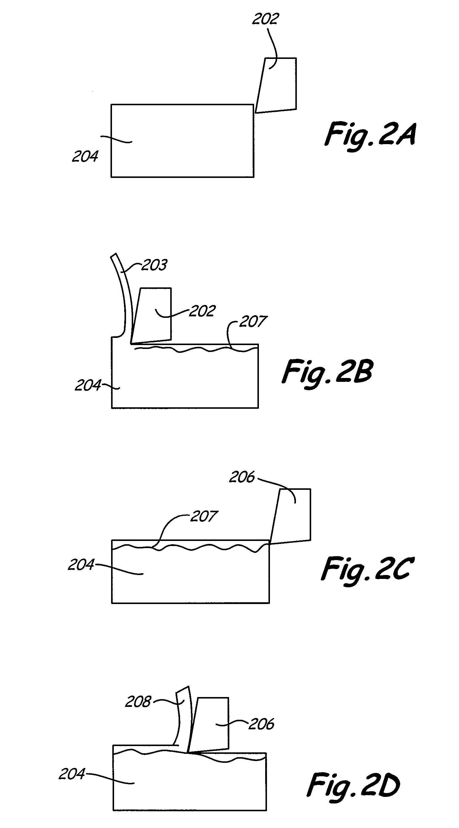
[0005] The present invention, according to one embodiment, is a method for cutting metal including providing a rotating cutting tool, making a first cut in the material using a first tooth of the cutting tool, such that an amount of heat is conducted into the material, and making a second cut in the material using a second tooth of the cutting tool, before the heat dissipates from the material, such that the heat softens the material and allows the second tooth to more easily cut the material.
[0007] In one embodiment of the present invention, the cutting tool makes a first cut in a workpiece material using a first tooth of the cutting tool, such that an amount of heat is conducted into the material. Then, the cutting tool makes a second cut in the material using a second tooth of the cutting tool, before the heat generated from the first cut dissipates from the material. The temperature generated from the first cut, the distance cut into the material from a top surface of the material by the first cut, and thermal diffusivity of the material, and time between the first cut and the second cut are configured and arranged that the heat generated from the first cut is fully utilized to efficiently and effectively softens the material allowing the second tooth to cut the material, thereby lowering a tool peak temperature characteristics for improving lifetime of the tool and material removal rate.
[0009] Where, T is a workpiece transient temperature (K), T(t=0) is an initial temperature (K) of the workpiece material, Ts is a temperature (K) of the workpiece material after the first tooth cut by the cutting tool, erf is an error function, X is a distance (mm) into the workpiece material from a top surface, α is a thermal diffusivity (mm2 / seconds) of the workpiece material, and t is the time (seconds) between the first tooth cut and the second tooth cut. The result of cutting the workpiece material using the HFTP regime is a reduction in specific cutting forces, high utilization of heat, lower peak tool temperatures, higher tool life, and improved material removal rates. It is noted that K, mm, mm2 / seconds, seconds, are metric units of the represented temperature, distance, thermal diffusivity, and time. It is appreciated that the other suitable unit systems can be used without departing from the principles of the present invention.

Problems solved by technology

Between each cutting path of successive teeth, heat is conducted into the workpiece and is lost to the environment.

Method used


Image

  • High frequency tooth pass cutting method
  • High frequency tooth pass cutting method
  • High frequency tooth pass cutting method

Examples


Embodiment Construction

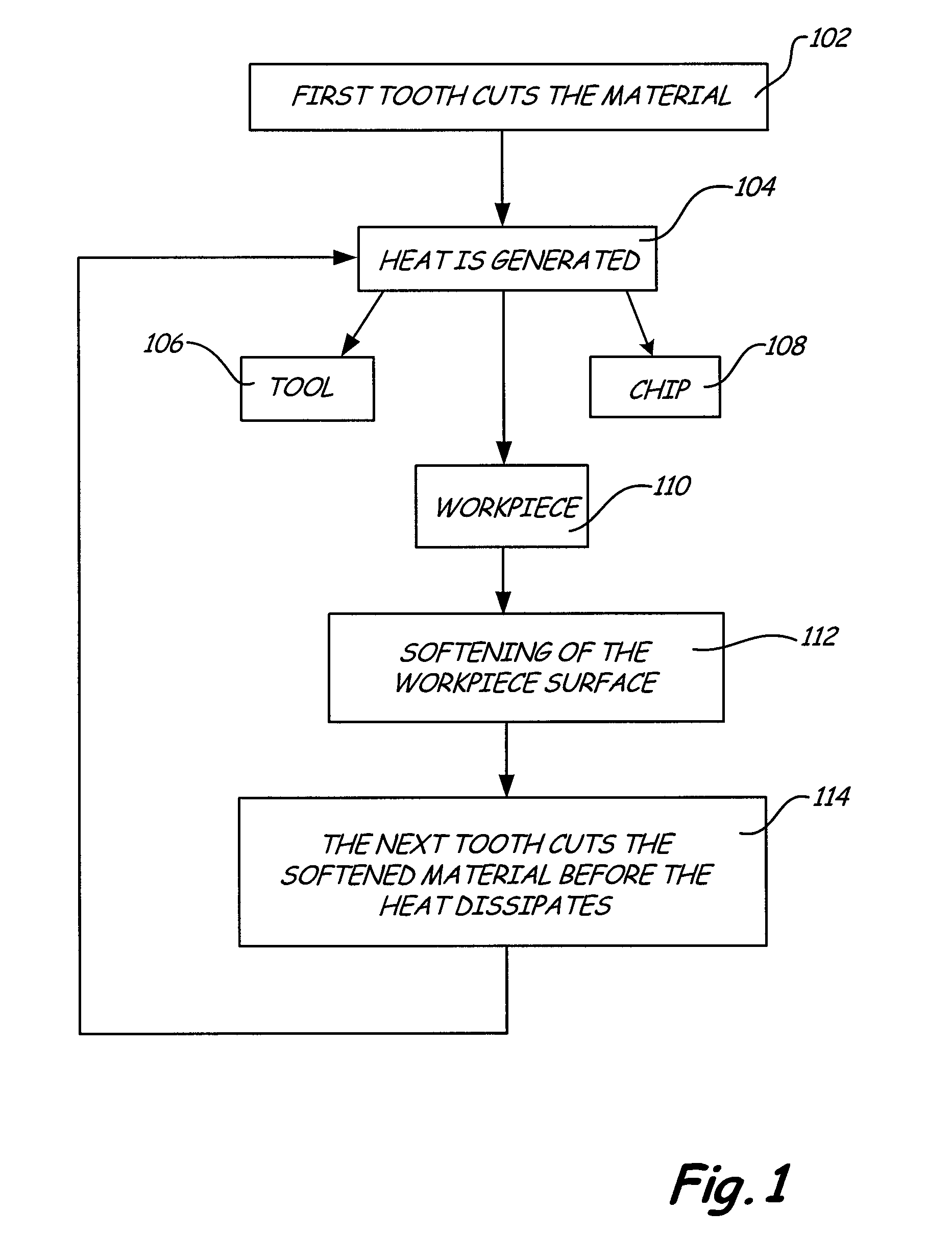
[0019]FIG. 1 is a flow chart showing a method 100 of cutting materials according to the present invention. As shown in FIG. 1, the first tooth of a multiple tooth cutting tool cuts the workpiece (block 102). This cutting process generates heat caused by forces between the cutting tool and the workpiece (block 104). Generally, this heat is distributed into three portions. One portion of the heat goes into the cutting tool (block 106), another portion goes into the chip or waste created by the cut (block 108), and the remaining portion goes into the workpiece (block 110). The heat conducted into the workpiece softens the surface of the workpiece (block 112). Depending on the thermal properties of the workpiece material, this heat from the surface gets transported into the bulk of the workpiece at a particular rate of conduction. The next tooth then cuts the workpiece before too much of the heat is transferred into the bulk of the workpiece (block 114). This process results in cutting ...


PUM

PropertyMeasurementUnit
Angleaaaaaaaaaa
Diameteraaaaaaaaaa
Timeaaaaaaaaaa

Abstract

A method of cutting a material is provided. In one embodiment, the method includes providing a cutting tool having a number of teeth with a cutting frequency of at least 95 teeth-per-second; rotating the cutting tool at a rotational speed at or below 10,000 revolutions per minute; making a first cut in the material using a first tooth of the cutting tool, an amount of heat being conducted into the material; making a second cut in the material using a second tooth of the cutting tool, before the heat generated from the first cut dissipates from the material, wherein the heat softening the material that allows the second tooth to more easily cut the material.

Description

CROSS-REFERENCE TO RELATED APPLICATION(S) [0001] This application is a Continuation-In-Part patent application of U.S. patent application Ser. No. 11 / 319,006, filed on Dec. 27, 2005, which is a continuation application of U.S. patent application Ser. No. 10 / 408,966, filed Apr. 8, 2003, now abandoned, which claims priority to U.S. provisional patent application No. 60 / 370,777 filed Apr. 8, 2002; the subject matters of which are incorporated herein by reference.FIELD OF THE INVENTION [0002] The present invention relates to an apparatus and method of cutting materials utilizing a rotating cutting tool. More specifically, the invention includes a cutting process that uses the heat generated by the cutting process to more efficiently cut materials. BACKGROUND OF THE INVENTION [0003] In the process of metal cutting, when a tool cuts a metal, heat is generated by shear stresses, plastic deformation, and friction in the cutting region. Generally this heat is distributed into three regions. ...

Claims


Application Information

Patent Timeline
IPC IPC(8): B23C3/00
CPCY10T409/303808B23C3/00
Inventor MARUSICH, TROY D.MARUSICH, KERRY J.
Owner THIRD WAVE SYST
Learn More